
Metal-inteference-resisting dipole antenna

a dipole antenna and interference resistance technology, applied in the direction of antenna couplings, resonance antennas, radiating element structural forms, etc., can solve the problems of increasing the complexity of the configuration of the internal circuit of the electronic device, the obvious reduction of the operation efficiency and the limited configuration of the dipole antenna

Active Publication Date: 2020-09-22
INVENTEC PUDONG TECH CORPOARTION +1
View PDF4 Cites 0 Cited by
  • Summary
  • Abstract
  • Description
  • Claims
  • Application Information

AI Technical Summary

Benefits of technology

The design effectively mitigates metal interference, maintaining operational efficiency while reducing the antenna's footprint within electronic devices, enabling more flexible and efficient internal configurations.

Problems solved by technology

Also, when there are metal properties closed to the dipole antenna, the operational efficiency of the dipole antenna will be obviously decreased.
However, in order to meet the demand of the people for the electronic device with both of the variety functions and the quality appearance, in the present market, the configuration of the internal circuits in the electronic device is more and more complex, and there're more and more electronic devices configured with the metal housing.
Hence, the configuration of the dipole antenna is limited by said above properties, and the problem thereof still needs to be improved.

Method used


Image

  • Metal-inteference-resisting dipole antenna
  • Metal-inteference-resisting dipole antenna
  • Metal-inteference-resisting dipole antenna

Examples


Embodiment Construction

[0012]In the following detailed description, for purposes of explanation, numerous specific details are set forth in order to provide a thorough understanding of the disclosed embodiments. It will be apparent, however, that one or more embodiments may be practiced without these specific details. In other instances, well-known structures and devices are schematically shown in order to simplify the drawings.

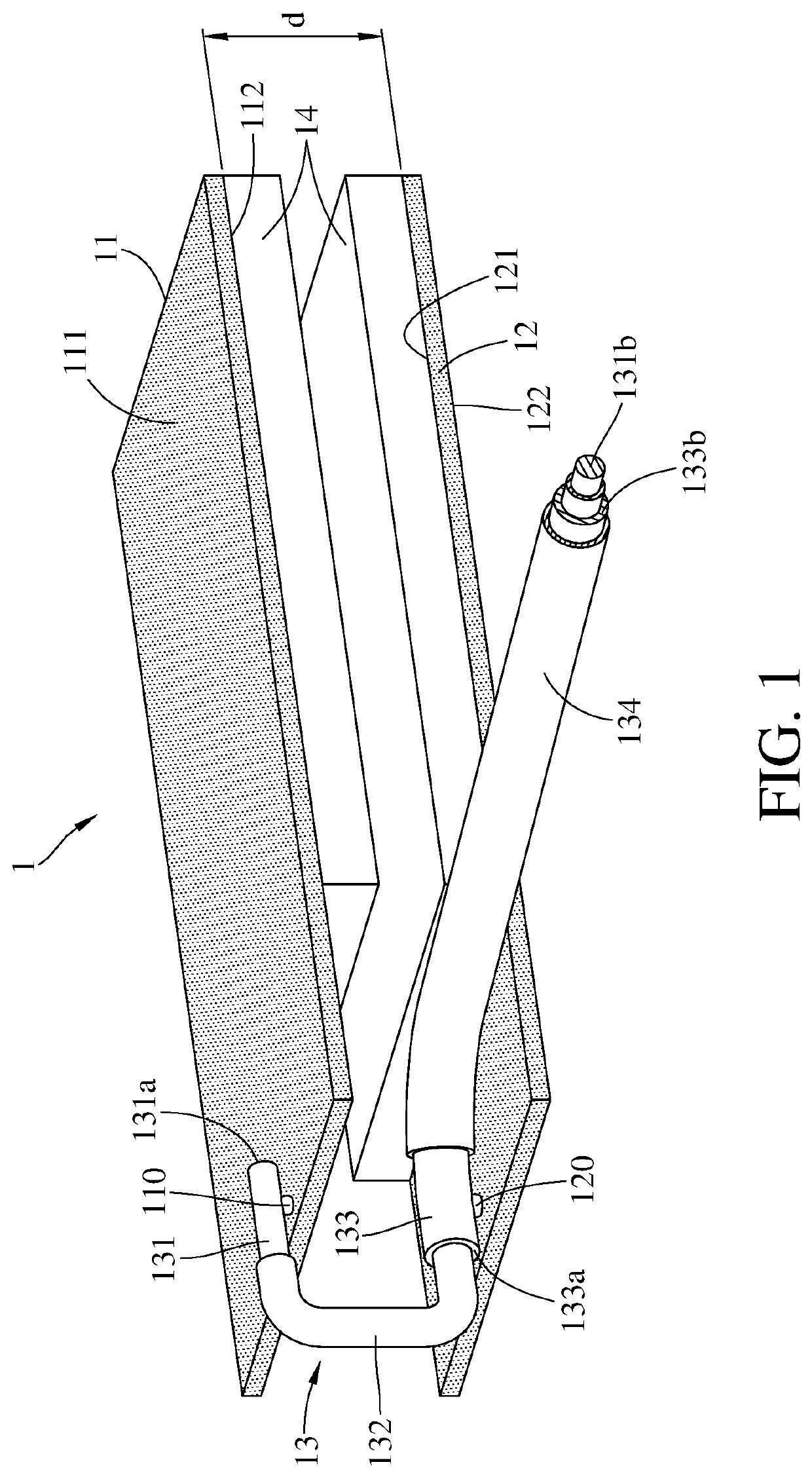
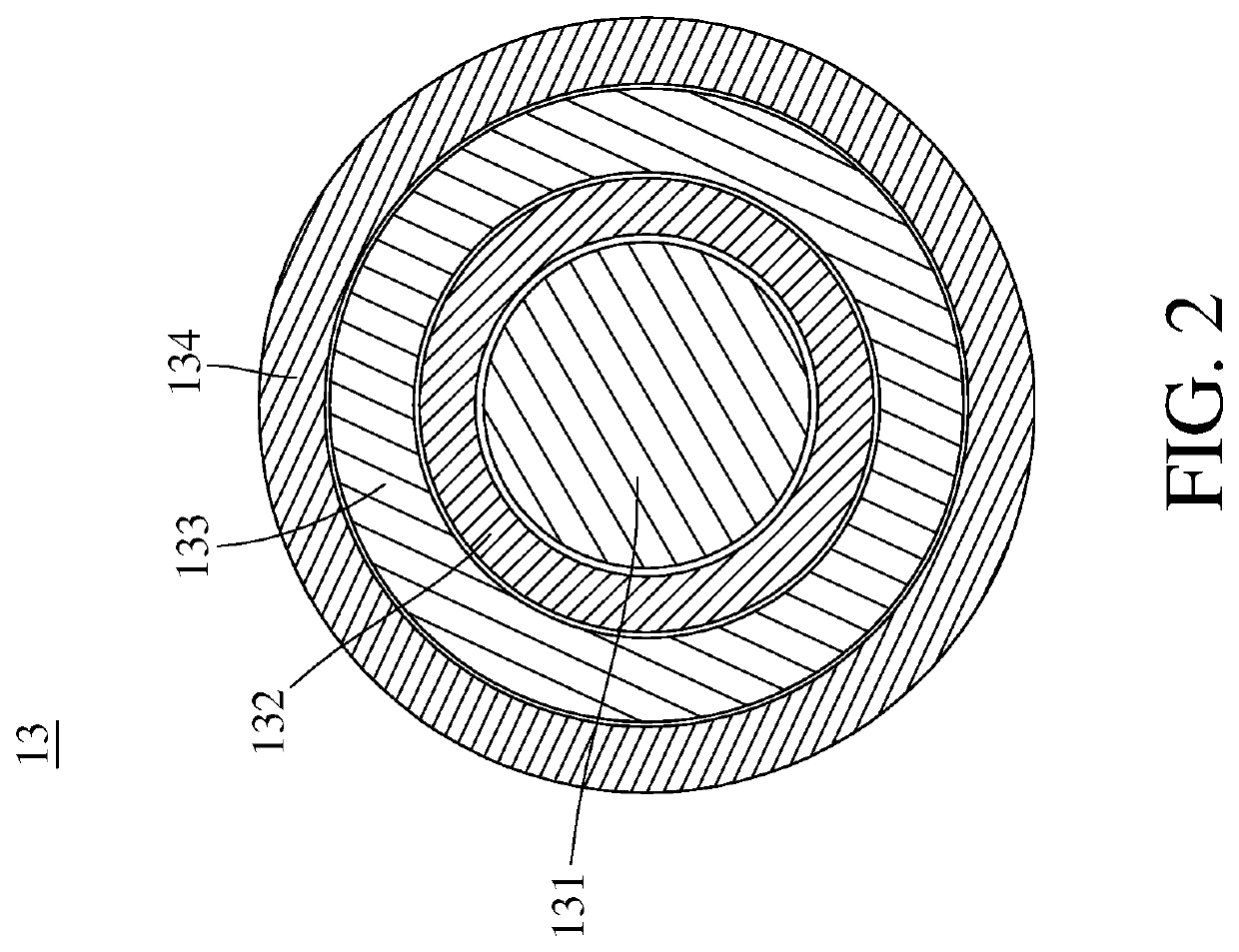
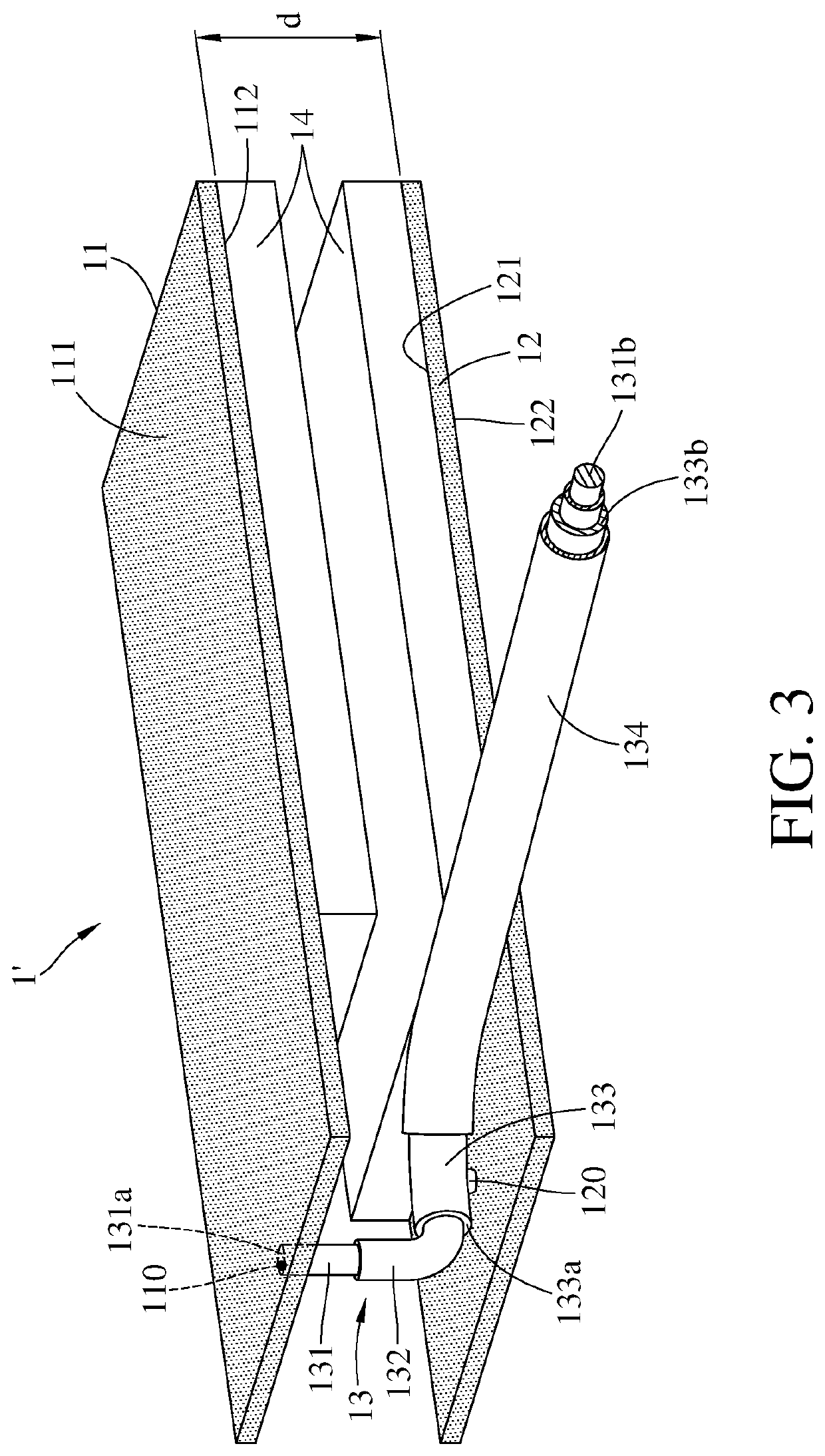
[0013]Please refer to FIG. 1, wherein FIG. 1 is the structure diagram of the metal-interference-resisting dipole antenna 1 in an embodiment based on this disclosure. As FIG. 1 shows, the dipole antenna 1 comprises a first metal plane 11, a second metal plane 12, a cable 13 and an antenna insulation layer 14. The first metal plane 11 and the second metal plane 12 may be the plane and be parallel to each other. Also, the first metal plane 11 and the second metal plane 12 are preferable to have identical shapes and sizes. On the other hand, the first metal plane 11 and the second meta...


PUM


Abstract

A metal-interference-resisting dipole antenna comprises a first metal plane, a second metal plane and a cable; the cable comprises an inner conductor, an insulation layer and an outer conductor, and the inner conductor comprises a first inner connecting end electrically connected to the first metal plane, and a second inner connecting end adapted for receiving the first feed signal; the insulation layer partly covers the inner conductor, wherein the outer conductor is disposed at the outer of the insulation layer corresponding to the inner conductor, and the outer conductor is electrically insulated from the inner conductor; the outer conductor has a first outer connecting end and a second outer connecting end, and the first outer connecting end is electrically connected to the second metal plane, and the second outer connecting end is adapted for receiving the second feed signal.

Description

CROSS-REFERENCE TO RELATED APPLICATIONS[0001]This non-provisional application claims priority under 35 U.S.C. § 119(a) on Patent Application No(s). 201811425351.1 filed in China on 27, Nov., 2018 the entire contents of which are hereby incorporated by reference.BACKGROUND1. Technical Field[0002]The disclosure relates to a dipole antenna, more particularly to the metal-interference-resisting dipole antenna.2. Related Art[0003]Since the technology of the wireless communication is already grown completely, different antennas have been disposed in various electronic devices. Additionally, since the dipole antenna has the simple structure and is early to be applied, the dipole antenna has been widely used presently.[0004]In general, the traditional dipole antenna is made by two coplanar metal planes and a cable connected between the two metal planes, so the area is larger than other components in the electronic device. Also, when there are metal properties closed to the dipole antenna, t...

Claims


Application Information

Patent Timeline
Patent Type & Authority Patents(United States)
IPC IPC(8): H01Q9/04H01Q1/38H01Q19/13
CPCH01Q9/0435H01Q1/38H01Q9/0414H01Q19/138H01Q1/36H01Q1/50H01Q1/52H01Q1/526H01Q9/28
Inventor LIN, YUAN SHENG
Owner INVENTEC PUDONG TECH CORPOARTION
Learn More