Wireless microphone system, receiving apparatus and wireless synchronization method

a microphone system and wireless synchronization technology, applied in the direction of synchronisation arrangement, mouthpiece/microphone attachment, microphone structure association, etc., can solve the problems of high probability that the plurality of master devices do not, clock deviation, and audio nois

Active Publication Date: 2020-09-29
PANASONIC INTELLECTUAL PROPERTY MANAGEMENT CO LTD
View PDF12 Cites 0 Cited by
  • Summary
  • Abstract
  • Description
  • Claims
  • Application Information

AI Technical Summary

Benefits of technology

[0008]In view of the related art described above, an object of the present disclosure is to provide a receiving apparatus, and a wireless synchronization method capable of precisely realizing wireless synchronization between the respective wireless microphone systems and supporting an output of a high-quality audio signal between the respective wireless microphone systems even in an environment where a coexistent area exists in the coverage areas of the plurality of wireless microphone systems.
[0012]According to the present disclosure, even in an environment where the coexistent area exists in the coverage areas of the plurality of wireless microphone systems, wireless synchronization between the respective wireless microphone systems can be precisely realized and an output of a high-quality audio signal between the respective wireless microphone systems can be supported.

Problems solved by technology

In one wireless microphone system, in a case where a plurality of master devices perform wireless communication with a plurality of microphone slave devices according to respectively independent clocks, there is a high probability that the plurality of master devices do not operate according to the same clock and a clock deviation may occur.
In this case, there is a problem that a collision of audio signals input from the master unit to a mixing and receiving apparatus may occur and audio noise may occur.
For this reason, in a case where the clock deviation occurs between the master devices as references in the different wireless microphone systems, there is a high probability that wireless signals transmitted from the respective wireless systems collide with each other during a long time.
As a result, there is a high possibility that interference in the audio signal occurs and audio noise occurs.
For example, in a case of performing a handover in which the microphone slave device transitions from the wireless microphone system, to which the microphone slave device currently belongs, to another wireless microphone system, if a clock deviation occurs between the wireless microphone systems, audio communication from the microphone slave device to the master device cannot be smoothly performed.

Method used


Image

  • Wireless microphone system, receiving apparatus and wireless synchronization method
  • Wireless microphone system, receiving apparatus and wireless synchronization method
  • Wireless microphone system, receiving apparatus and wireless synchronization method

Examples


embodiment 1

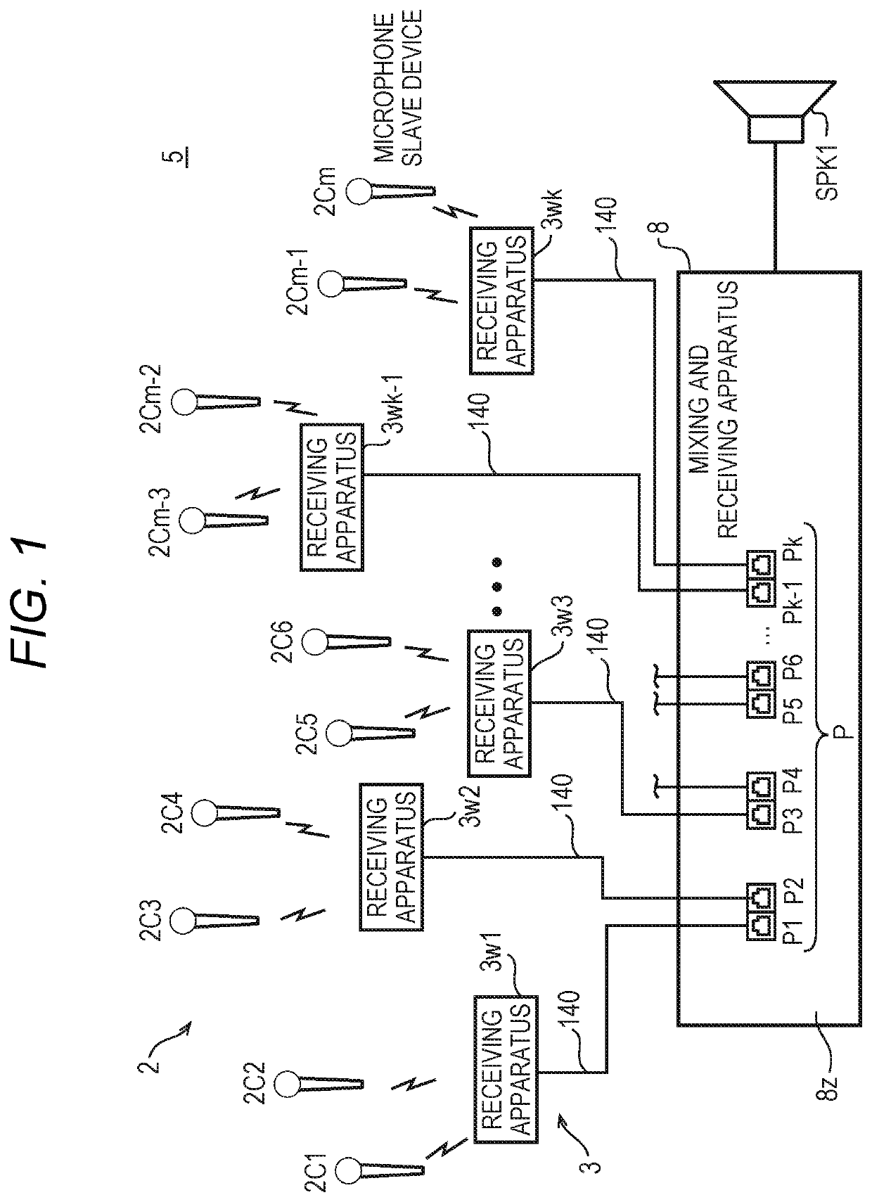
[0040]In the wireless microphone system according to Embodiment 1, a plurality of receiving apparatuses are arranged at regular intervals in a room such as a hall. Each of the receiving apparatuses functions as a master device of a communication target for one or more microphone slave devices (that is, wireless microphones). Each of the microphone slave devices can be recognized by a person (for example, a user of the microphone slave device). During communication with the master device, while the handover is performed as the person moves, the microphone slave device can move between the master devices in the same wireless microphone system. In addition, the microphone slave device also can move while performing the handover from the wireless microphone system, to which the microphone slave device currently belongs, including the plurality of master devices to another wireless microphone system.

[0041]FIG. 1 is a diagram schematically illustrating a system configuration example of a ...

modification example 1 of embodiment 1

[0090]In each of the wireless microphone systems, in a case where wiring between the mixing and receiving apparatus and each of the receiving apparatuses becomes long, a delay occurs between the mixing and receiving apparatus and each of the receiving apparatuses. It is necessary to recognize a delay time so that a clock deviation in the radio frame does not occur due to the delay time.

[0091]FIG. 13 is a diagram illustrating measurement of the delay time between the mixing and receiving apparatus 8 and the receiving apparatus 3 according to Modification Example 1 of Embodiment 1. The mixing and receiving apparatus 8 transmits a delay time measurement reference signal T0 to the reference receiving apparatus (for example, the receiving apparatus 3w1). When receiving the delay time measurement reference signal T0 from the mixing and receiving apparatus 8, the reference receiving apparatus (for example, the receiving apparatus 3w1) returns a delay time measurement response signal T1 imm...

modification example 2 of embodiment 1

[0099]In Embodiment 1 described above, the sub reference receiving apparatus of the sub wireless microphone system is synchronized with the wireless control signal transmitted from the main reference receiving apparatus of the main wireless microphone system, but the sub reference receiving apparatus of the sub wireless microphone system may be synchronized with the other system.

[0100]FIG. 15 is a diagram illustrating that synchronization of the sub wireless microphone system 5B using another system 6 according to Modification Example 2 of Embodiment 1 is established. The sub reference receiving apparatus 3Bw1 registers a communication device ID to be searched of the other system 6 in the storage unit 25 in advance so as to establish the wireless synchronization. The sub reference receiving apparatus 3Bw1 searches for a communication device having the registered communication device ID, receives a signal sg1 transmitted from a communication device 301, and generates the reference ti...


PUM


Abstract

One of the plurality of first slave receiving apparatuses which serves as a reference first slave receiving apparatus repeatedly transmits a wireless control signal for controlling synchronization between a first receiving apparatus segment and a second receiving apparatus segment. One of the plurality of second slave receiving apparatuses which serves as a reference second slave receiving apparatus transmits a reference timing signal for performing synchronization in the second receiving apparatus segment including the reference second slave receiving apparatus to the second master receiving apparatus in synchronization with the wireless control signal. The second master receiving apparatus transmits a synchronization timing signal for performing synchronization in the second receiving apparatus segment including the second master receiving apparatus to another one of the plurality of second slave receiving apparatuses in the second receiving apparatus segment including the second master receiving apparatus, in response to the reference timing signal.

Description

BACKGROUND OF THE INVENTION1. Field of the Invention[0001]The present disclosure is related to a wireless microphone system, a receiving apparatus, and a wireless synchronization method which receive an audio signal transmitted between a plurality of microphones by using time division multiplex communication.2. Background Art[0002]In the related art, there is known a wireless microphone system which transmits an audio signal collected by a microphone, by using wireless communication. The wireless microphone system includes a plurality of microphone slave devices and a receiving apparatus (master device) which receives the audio signal transmitted from the microphone slave device through a communication channel established with each of the microphone slave devices. The master device includes a speaker and causes the speaker to output the audio signal collected by each of the microphone slave devices. Since the wireless microphone system can flexibly correspond to a use environment, t...

Claims


Application Information

Patent Timeline
Patent Type & Authority Patents(United States)
IPC IPC(8): H04W4/80H04R1/08H04R1/04H04W56/00H04J3/06
CPCH04R1/04H04J3/0658H04R1/083H04R2420/07H04R3/005H04J3/0605
Inventor MIYAHARA, TAKESHINAKAGAWA, KATSUMIKITAGO, RYOSUKESASAKI, HISAYUKI
Owner PANASONIC INTELLECTUAL PROPERTY MANAGEMENT CO LTD
Why Eureka
Try Eureka