Mixed flow optimized turbine

a technology of mixed flow and optimized turbines, which is applied in the direction of gas turbine plants, blade accessories, machines/engines, etc., can solve the problems of negative impact on the efficiency of the cycle, increase of axial extension, adversely affect the rotary dynamics of machines, etc., and achieve the effect of reducing the inevitable fluid scrambling and lowering the impact on the turbine's performan

Active Publication Date: 2020-10-06
TURBODEN
View PDF8 Cites 0 Cited by
  • Summary
  • Abstract
  • Description
  • Claims
  • Application Information

AI Technical Summary

Benefits of technology

[0025]As the injection of working fluid or even its extraction have a minimal or in any case negligible impact on the turbine's performance, it is necessary that the speed vectors of both the main flow (the one which performs the full expansion in the turbine) and the second flow (the one which is injected or extracted) are almost coincident regarding intensity, direction and orientation. Any deviation from such condition, obviously ideally, will however lead to a disorder of the main flow, due to enthalpy leakage of the working fluid. The stator with angular blades works better than any other stator or rotor group in the injection or extraction of fluid for the “curved” geometry of such stage. The insertion in this zone of the injection or extraction of fluid permits to make more accurately the combination or mixing between the two flows, thus reducing the inevitable fluid scrambling with different speeds in terms of absolute value and / or direction and resulting in turbulent leakages, with a lower impact on the turbine's performance, so ensuring the benefits previously outlined in terms of overall cycle efficiency.
[0026]Furthermore, the injection of the second flow of working fluid into the angular stator stage causes the injected flow to benefit from the subsequent expansion of the main fluid within the same stage so that it can more easily align with the main flow lines. If the injection occurs instead within a duct without blades (for example in the space between a rotor array and the next stator array), the mixing between the two streams would be in a less controlled and regular way.

Problems solved by technology

As the user requires heat at a higher temperature than room temperature, the condensing temperature rises accordingly, with a negative impact on the efficiency of the cycle (if compared with similar power generation solutions just for electrical production, on the other hand it can benefit from a condensation temperature just slightly above ambient).
Depending on the adopted solution, such injection or extraction may result in an increase of the axial extension of the turbine, which can adversely affect the rotary dynamics of machines, particularly if the turbine has a cantilever mounting with respect to its bearings.

Method used


Image

  • Mixed flow optimized turbine
  • Mixed flow optimized turbine
  • Mixed flow optimized turbine

Examples


third embodiment

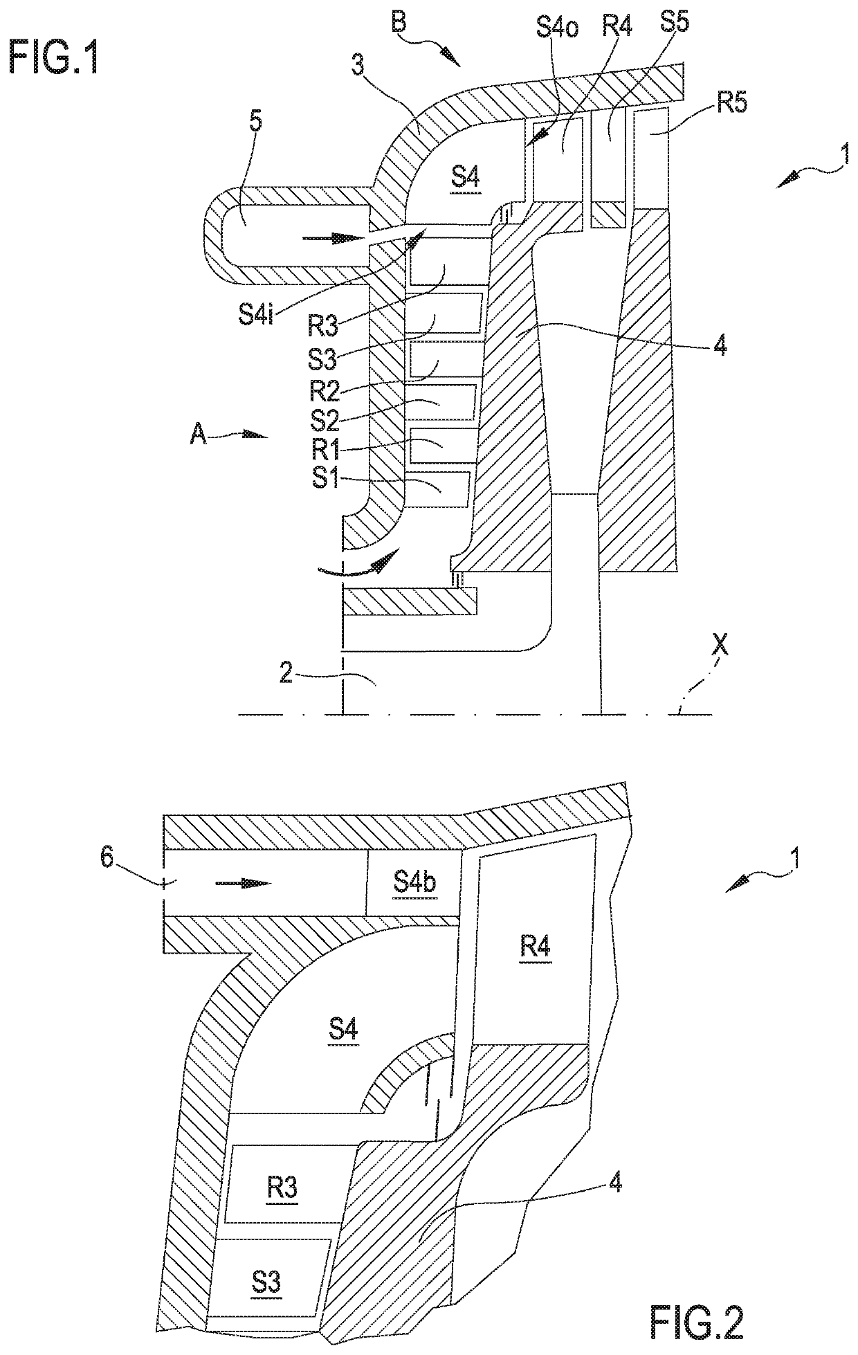
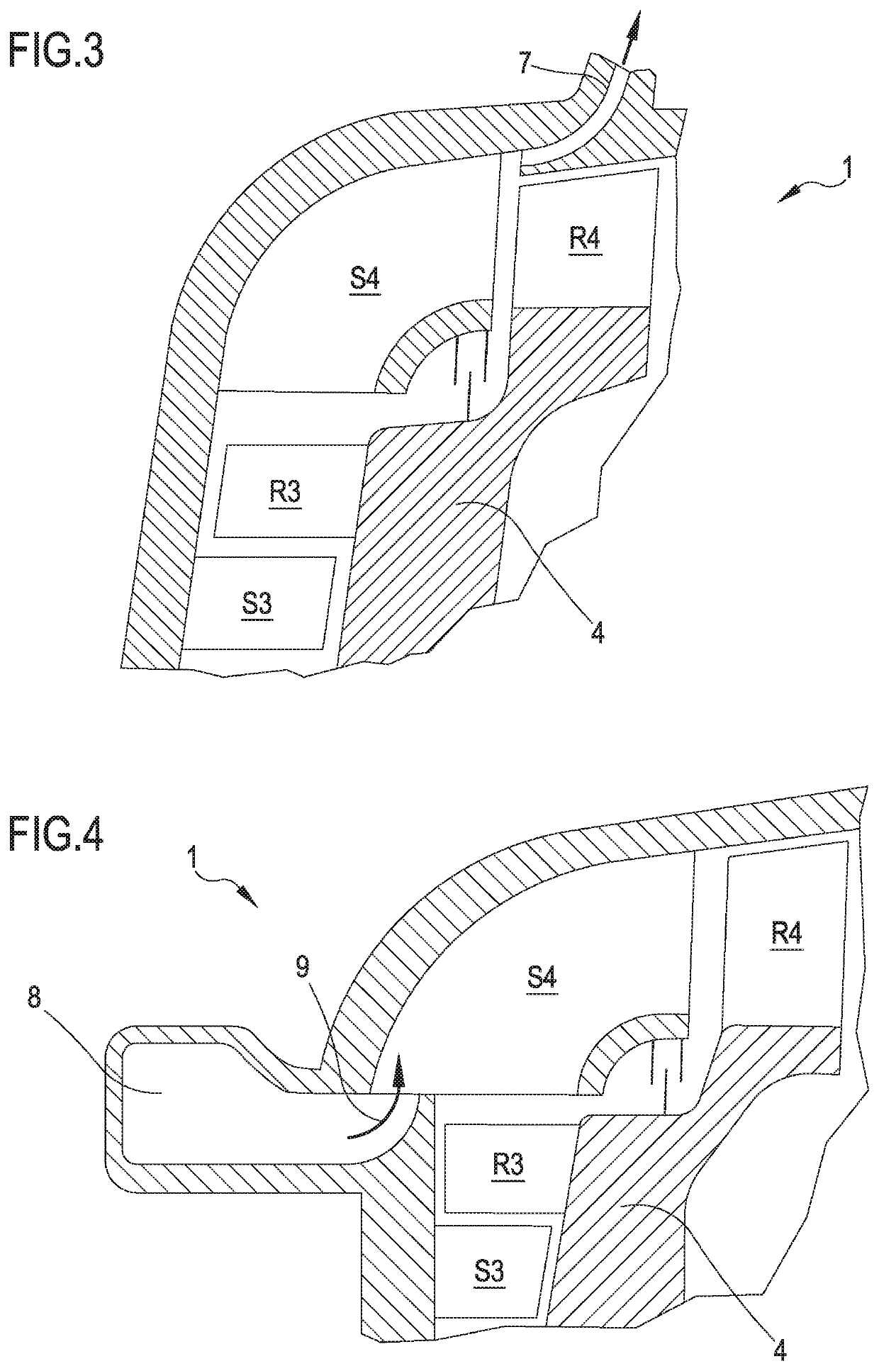
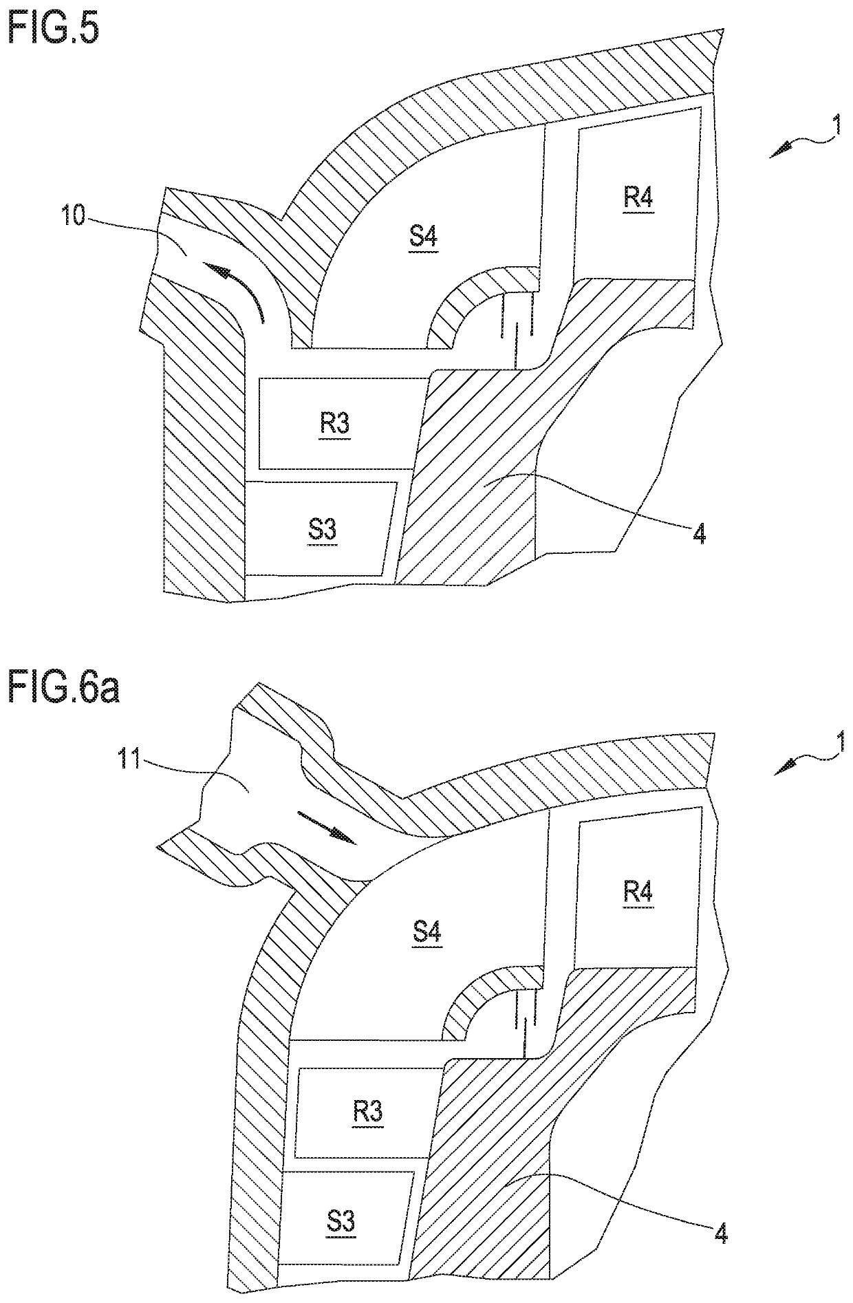
[0058]With reference to FIGS. 6a and 6b, the present invention is shown therein. Also in this configuration, the Figure shows the last radial stage S3-R3, the angular stator stage S4 with angular blades and the first axial rotor R4. In this case, the injection or extraction of working fluid takes place by means of a chamber or duct 11, in an intermediate position of the stator angular stage S4, preferably so that the divert of flow at the meridian plane has already occurred about as a half, making it easier and clearer to position the supply chamber, which does not disturb either the radial or the axial stages. In this way, both in the case of injection and of extraction, there is still a substantial further expansion and acceleration of the stator flow path, allowing for a fluid resetting and a reduction in flow vortices.

[0059]A fourth configuration of the invention is shown in FIG. 7.

[0060]This FIG. 7 still shows the same partial section of the mixed flow turbine of FIG. 1. This c...

fifth embodiment

[0061]A further vapor injection solution is shown in FIG. 8. This Figure shows a partial perspective view of the angular stator stage S4 with angular blades. According to this fifth embodiment, the main flow outgoing from the centrifugal radial stages is conveyed by the blades of the stator angular stage S4 in an axial direction as in the previous cases. However, the stator angular stage S4 is so shaped that each duct S41, S42 of the blades and so on diverges by detaching from the adjacent one, leaving space for the inlet of the second flow, is also accelerated and driven by appropriate stator ducts S4c. In this way, the first axial rotor will have inlet sectors alternately powered by the main flow and by the second flow.

[0062]FIG. 9 shows an embodiment equivalent to that of FIG. 8, but in this case the same principle is applied to the case of working fluid extraction: the vapor outgoing from the rotor stage R3 will alternately supply the blade ducts S41, S42, . . . connected to the...


PUM


Abstract

A mixed flow turbine (1) for the expansion phase of steam thermodynamic cycles of an organic Rankine cycle provided with a first section (A) in which a first expansion of a main flow of working fluid takes place, in a substantially radial direction having at least one stator stage (S1, S2, . . . Sn) and at least one rotor stage (R1, R2, . . . Rn) of a second section (B) in which a second expansion of the main flow of the working fluid takes place in a substantially axial direction having at least one stator stage and at least one rotor stage and, between the first and the second section, with at least one angular stator stage (S4) comprising an array of angular blades which deflect the main flow of working fluid from the initial radial direction to a substantially axial direction. The turbine (1) is provided with means for injection (60) and / or means for extraction (70) of a second flow of working fluid, placed in proximity of the stator stage (S4).

Description

BACKGROUND OF THE INVENTION1. Field of the Invention[0001]The present invention relates to a mixed flow turbine for the expansion phase of thermodynamic vapor cycles, in particular an organic Rankine cycle (hereinafter also called ORC cycle). The turbine is optimized in its performance as being provided with injection and / or extraction means of an organic working fluid.2. Brief Description of the Prior Art[0002]As is known, a thermodynamic cycle is defined as a finite succession of thermodynamic transformations (such as isotherms, isocores, isobars or adiabatics) at the end of which the system returns to its initial state. In particular, an ideal Rankine cycle is a thermodynamic cycle made of two adiabatic and two isobaric transformations, with two phase changes from liquid to vapor and from vapor to liquid. Its aim is to transform heat into work. Such cycle is generally mainly adopted in power generation plants for the production of electric energy, and uses water as engine fluid, ...

Claims


Application Information

Patent Timeline
Patent Type & Authority Patents(United States)
IPC IPC(8): F01D9/06F01D5/04F02C9/18F01D9/04
CPCF01D9/06F01D5/041F01D9/045F02C9/18F05D2220/32F05D2240/128
Inventor GAIA, MARIOBINI, ROBERTOCOLOMBO, DAVIDE
Owner TURBODEN
Why Eureka
Try Eureka