Vertically mounted and magnetically driven power generation apparatus

a power generation apparatus and vertical mounting technology, applied in the direction of windings, magnetic circuit rotating parts, magnetic circuit shapes/forms/construction, etc., can solve the problems of ineffective power generation of generation apparatuses, inability to effectively convert kinetic energy provided by the source of kinetic energy into electrical energy, and prone to left-right swing of magnetically driven power generation apparatuses, so as to reduce the ground area occupied, reduce left-right swing, and enhance rotational stability

Active Publication Date: 2020-10-06
WONG SHOU CHENG
View PDF12 Cites 2 Cited by
  • Summary
  • Abstract
  • Description
  • Claims
  • Application Information

AI Technical Summary

Benefits of technology

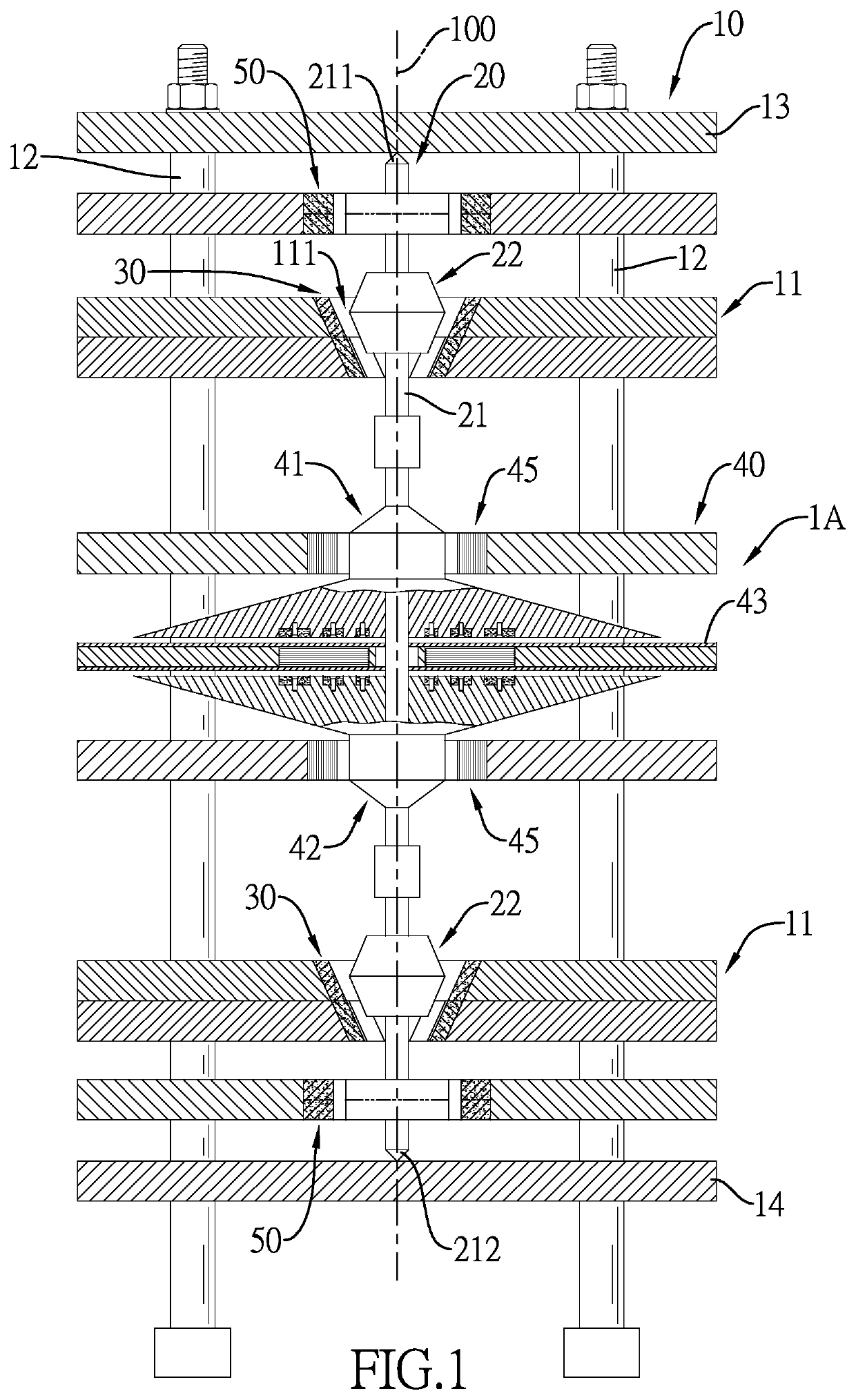
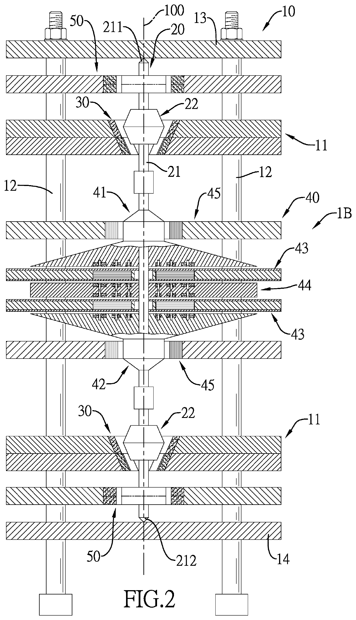
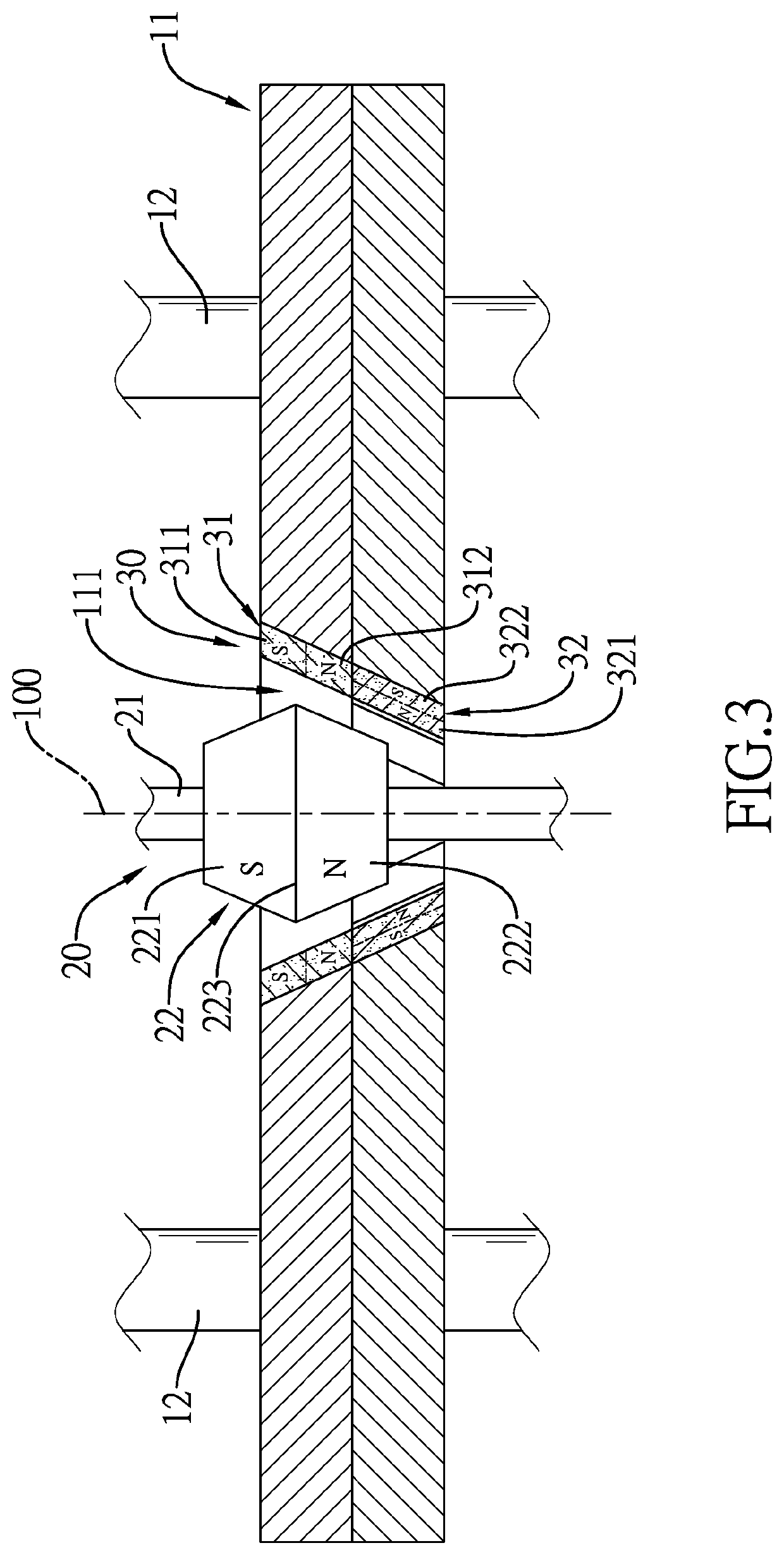
[0086]The benefits achieved by the present invention include the transmission mechanism vertically mounted in the support frame, the at least one power generator connected with the transmission mechanism, and multiple magnetic drive assemblies mounted inside the respective shelves of the support frame for the transmission mechanism to be vertically and suspendedly rotated within the support frame in a frictionless manner as a result of magnetic repulsion effect generated between the magnetic drive assemblies and the magnetic driven members of the transmission mechanism. In addition, in view of such vertically assembled structure, the vertically mounted and magnetically driven power generation apparatus can effectively reduce a ground area occupied thereby and can be therefore installed in a factory with a limited space.
[0087]The vertically mounted and magnetically driven power generation apparatus further includes multiple magnetically stabilizing modules mounted inside the support frame and providing radial magnetic repulsion to the transmission mechanism, thereby reducing left-and-right swing of the transmission mechanism upon rotation in the support frame, enhancing rotational stability upon high-speed operation, and attaining improved power generation efficiency.
[0088]The vertically mounted and magnetically driven power generation apparatus further includes a top board and a bottom board mounted in the support frame, and the spindle of the transmission mechanism has a top end and a bottom end in point contact with the top board and the bottom board respectively to further enhance the rotational stability of the transmission mechanism upon rotation.
[0089]The vertically mounted and magnetically driven power generation apparatus further includes at least one motor. The rotor of each of the at least one motor has a flywheel body being disc-shaped with an up-down symmetry, such that good rotational stability of the rotor of the motor can be maintained upon high-speed rotation. Also because the flywheel body of the rotor is securely mounted on the spindle, the rotational stability and rotational inertia of the transmission mechanism can be further enhanced.
[0090]In the event that the vertically mounted and magnetically driven power generation apparatus is a large-size power generation apparatus, each magnetically stabilizing module can further include two second permanent magnet rings securely mounted inside the positioning board and vertically spaced apart from each other by a gap. Additionally, the first permanent magnet ring and the inner permanent magnet are located between the two second permanent magnet rings, and the inner permanent magnet is suspended among the first permanent magnet ring and the two second permanent magnet rings by way of magnetic repulsion in an axial direction along the center axis, such that the transmission mechanism can be suspended within the support frame by the axial magnetic repulsion effect. By virtue of the axial repulsion effect provided by the two second permanent magnet rings of the magnetically stabilizing module to the transmission mechanism, up-and-down vibration generated upon rotation of the transmission mechanism can be reduced, thereby increasing rotational stability of the transmission mechanism vertically suspended in the support frame and enhancing the power generation efficiency.

Problems solved by technology

Owing to energy loss arising from frictional resistance occurring in the transmission assembly, the kinetic energy provided by the source of kinetic energy fails to be effectively converted to electrical energy.
As a result, for so long conventional power generation apparatuses have the drawbacks of ineffective power generation due to energy loss in the transmission assembly.
However, the aforementioned vertically mounted and magnetically driven power generation apparatuses are prone to left and right swing along a radial direction upon rotation of the transmission shaft in the suspended and frictionless manner, especially when the transmission shaft is rotated at a high speed.
Such radial swing is adverse to transmission of kinetic energy through the transmission shaft.

Method used


Image

  • Vertically mounted and magnetically driven power generation apparatus
  • Vertically mounted and magnetically driven power generation apparatus
  • Vertically mounted and magnetically driven power generation apparatus

Examples


Embodiment Construction

[0106]With reference to FIGS. 1, 2 and 8, three embodiments 1A-1C of a vertically mounted and magnetically driven power generation apparatus in accordance with the present invention are shown. Each embodiment 1A-1C of the vertically mounted and magnetically driven power generation apparatus includes a support frame 10, a transmission mechanism 20, multiple magnetic drive assemblies 30, a power generator 40 and multiple magnetically stabilizing modules 50.

[0107]With reference to FIGS. 1 and 2, the support frame 10 includes multiple shelves 11 and multiple struts 12. The multiple shelves 11 are vertically arranged and are vertically spaced apart from each other. The multiple struts 12 are securely connected with the multiple shelves 11 to support the multiple shelves 11. The support frame 10 has a center axis 100 vertically and centrally passing through the support frame 10. Each shelf 11 has a through hole 111 that is formed through the shelf 11, tapers downwards, and may be a trunca...


PUM


Abstract

A vertically mounted and magnetically driven power generation apparatus includes a transmission mechanism vertically mounted in a support frame with a spindle thereof connected with a power generator. Multiple magnetic drive assemblies are respectively mounted inside multiple shelves of the support frame. By virtue of magnetic repulsion between the magnetic drive assemblies and multiple magnetic driven members mounted on the transmission mechanism, the spindle can be vertically and suspendedly rotated within the support frame. The power generation apparatus further includes multiple magnetically stabilizing modules that provide radial or axial magnetic repulsion to the transmission mechanism so as to reduce left-and-right swing or up-and-down vibration when the spindle is rotated within the support frame. Accordingly, the power generation apparatus can achieve superior stability and optimal power generation efficiency upon high-speed operation.

Description

BACKGROUND OF THE INVENTION1. Field of the Invention[0001]The present invention relates to a power generation apparatus and, more particularly, to a vertically mounted and magnetically driven power generation apparatus.2. Description of the Related Art[0002]Conventional power generation apparatuses usually adopt a transmission assembly to transmit kinetic energy provided from a source of kinetic energy to a power generation unit thereof. Owing to energy loss arising from frictional resistance occurring in the transmission assembly, the kinetic energy provided by the source of kinetic energy fails to be effectively converted to electrical energy. As a result, for so long conventional power generation apparatuses have the drawbacks of ineffective power generation due to energy loss in the transmission assembly.[0003]To cope with the issue of ineffective power generation in conventional power generation apparatuses, vertically mounted and magnetically driven power generation apparatuse...

Claims


Application Information

Patent Timeline
Patent Type & Authority Patents(United States)
IPC IPC(8): H02K3/46H02K1/27H02K16/00H02K7/18H02K7/02H02K53/00H02K5/04
CPCH02K7/025H02K7/1807H02K53/00H02K1/2793H02K16/00H02K3/46H02K5/04H02K49/108H02K1/2795
Inventor WONG, SHOU-CHENG
Owner WONG SHOU CHENG
Why Eureka
Try Eureka