
Jack-up rig for performing multiple independent operations simultaneously

a jack-up rig and independent technology, applied in the field of jack-up rigs, can solve problems such as space loss, and achieve the effects of increasing flexibility to an even higher level, facilitating a change of skidding directions, and easy extension

Active Publication Date: 2020-10-13
GRANT PRIDECO LP
View PDF15 Cites 1 Cited by
  • Summary
  • Abstract
  • Description
  • Claims
  • Application Information

AI Technical Summary

Benefits of technology

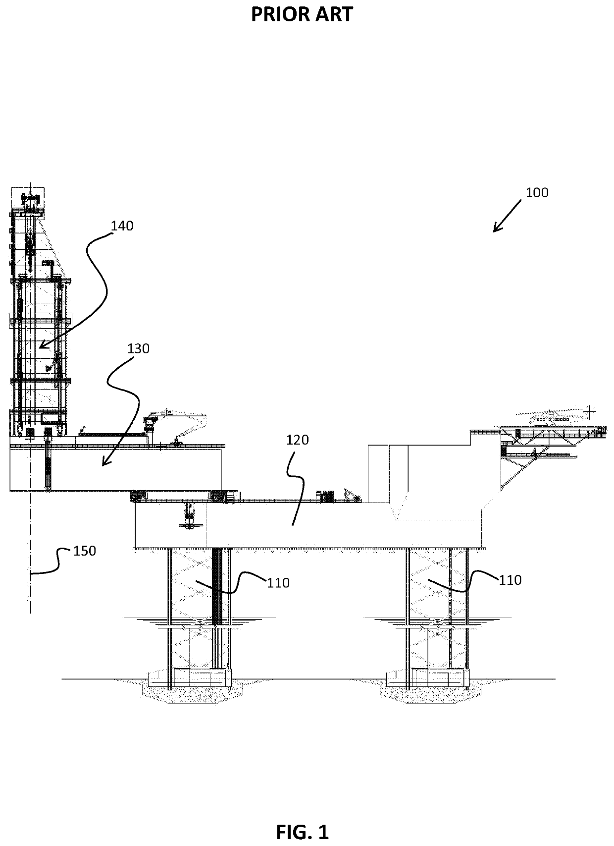
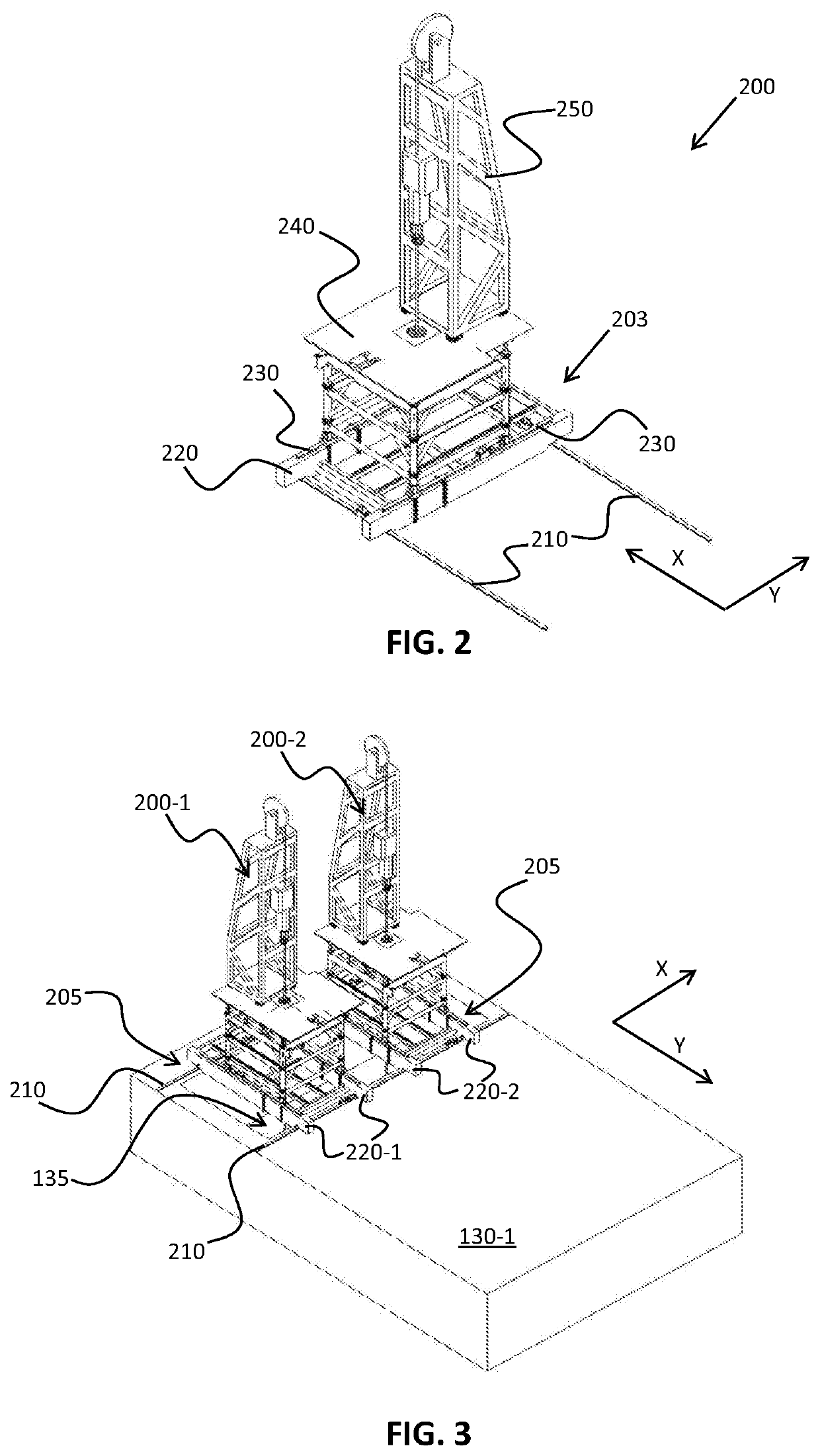
[0014]The effects of the jack-up rig in accordance with this disclosure are as follows. Two, preferably compact, drilling assemblies (i.e. derrick assemblies) are provided on a single cantilever platform. Moreover, these drilling assemblies are independently movable (within a plane parallel to the cantilever platform in both X-direction as well as Y-direction orthogonal to the X-direction) from each other. First of all, this leads to a cost-effective space saving solution for the cantilever, but also results in more flexible multiple-derrick (or drilling unit) jack-up rig. Furthermore, the respective drilling assemblies within the multiple derrick jack-up rig may be placed more quickly and more flexibly on the respective well targets, instead of having to modify two cantilever jack-up platforms as in one of the discussed prior art solutions. Furthermore, when two (movable) cantilevers are used, as in the prior art, this will always lead to a space loss, compared to the single (large) cantilever in accordance with this disclosure.
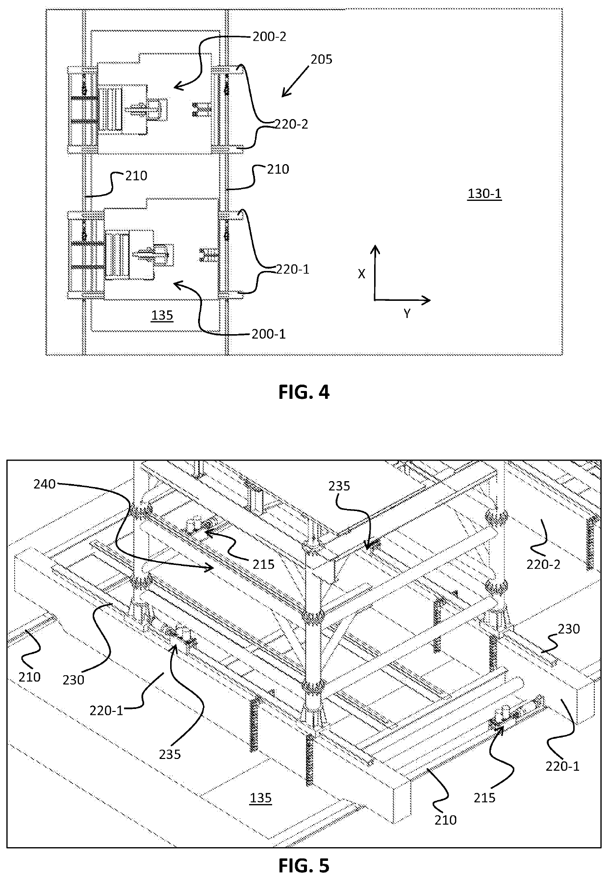
[0021]one respective drilling support structure on respective Y-direction rails of each one of the Y-direction support frames. This embodiment conveniently provides for a compact skid system for moving two (or more) drilling assemblies instead of one, i.e. two (or more) individual skid systems have been integrated into one, wherein the X-direction rails are effectively shared by said Y-direction support frames. Such skid system could also be referred to as a “dual-skid” or “twin-skid” and forms a very compact solution in terms of areal consumption on the cantilever platform.
[0026]one respective drilling support structure on each one of the XY-support frames. This, second, embodiment also provides for a compact skid system for moving two (or more) drilling assemblies instead of one, i.e. two (or more) individual skid systems have been integrated into one, wherein the XY-rails are effectively shared by said XY-support frames. A main difference with the earlier mentioned first embodiment is, however, that the second embodiment is more flexible, in that the respective drilling assemblies can exchange places completely, which is clearly not possible in the first embodiment. Expressed differently, each drilling assembly may move along the rails to any place that is free. In the detailed description below, an example is given with four sectors, but any number of sectors is possible, increasing the flexibility to an even higher level. In one variant of this embodiment, on respective crossings and corners, the rails are provided with interruptions to facilitate a change of skidding directions at the crossings. This is one way of providing XY-skidding, but there are also other ways.
[0027]In another embodiment of the jack-up rig in accordance with this disclosure, at least one further skid system is provided between each respective drilling support structure and respective XY-support frame for enabling at least one extra translation degree-of-freedom. This embodiment solves the potential problem of “blind spots” in the respective well pattern, i.e. well targets, which cannot be reached by the respective drilling assemblies, because they are effectively standing in each other's way. In the detailed description below, an example is given with only one extra pair of X-direction rails per XY-support frame, but they may be easily extended with an extra pair of Y-direction rails (on a respective frame).

Problems solved by technology

Furthermore, when two (movable) cantilevers are used, as in the prior art, this will always lead to a space loss, compared to the single (large) cantilever in accordance with this disclosure.

Method used


Image

  • Jack-up rig for performing multiple independent operations simultaneously
  • Jack-up rig for performing multiple independent operations simultaneously
  • Jack-up rig for performing multiple independent operations simultaneously

Examples


Embodiment Construction

[0044]Various illustrative embodiments of the present subject matter are described below. In the interest of clarity, not all features of an actual implementation are described in this specification. It will of course be appreciated that in the development of any such actual embodiment, numerous implementation-specific decisions must be made to achieve the developers' specific goals, such as compliance with system-related and business-related constraints, which will vary from one implementation to another. Moreover, it will be appreciated that such a development effort might be complex and time-consuming, but would nevertheless be a routine undertaking for those of ordinary skill in the art having the benefit of this disclosure.

[0045]The present subject matter will now be described with reference to the attached figures. Various systems, structures and devices are schematically depicted in the drawings for purposes of explanation only and so as to not obscure the present disclosure ...


PUM


Abstract

Disclosed is a jack-up rig that includes a cantilever platform mounted on a buoyant hull. At least two drilling assemblies are provided on the cantilever platform, each of the drilling assemblies being movable relative to the cantilever platform and being moveable independently from the other drilling assembly or assemblies. Each of the drilling assemblies is also movable within a plane that is parallel to the cantilever platform in both X-direction as well as Y-direction which is orthogonal to the X-direction.

Description

CROSS REFERENCE TO RELATED APPLICATIONS[0001]This application is a 35 U.S.C. § 371 national stage application of PCT / NO2017 / 050158 filed Jun. 14, 2017 and entitled “Jack-Up Rig for Performing Multiple Independent Operations Simultaneously”, which claims priority to European Patent Application No. 16176113.5 filed Jun. 24, 2016, each of which is incorporated herein by reference in their entirety for all purposes.STATEMENT REGARDING FEDERALLY SPONSORED RESEARCH OR DEVELOPMENT[0002]Not applicable.FIELD OF THE INVENTION[0003]The invention relates to a jack-up rig comprising a cantilever platform mounted on a buoyant hull, wherein said jack-up rig includes two or more drilling assemblies mounted thereon.BACKGROUND[0004]A jack-up rig is a floating drilling unit that can jack up on its legs and have the same stability as a fixed platform. In order to start a drilling operation, the jack-up rig will be towed to a target location, it will lower its legs on the sea floor and jack up above sea...

Claims


Application Information

Patent Timeline
Patent Type & Authority Patents(United States)
IPC IPC(8): E21B15/02E02B17/02E21B15/00
CPCE21B15/02E21B15/003E02B17/021E02B17/02
Inventor PLANO, MARCOBERGE, ROAR
Owner GRANT PRIDECO LP
Learn More