Method and device in UE and base station used for power adjustment

a technology of power adjustment and transmission method, applied in the direction of power management, signalling characterisation, wireless communication, etc., can solve the problems of new problem of uplink power adjustment and phr, and achieve the effect of reducing the complexity of uplink power control and signaling overhead, and avoiding waste of uplink resources

Active Publication Date: 2020-10-20
SHANGHAI LANGBO COMM TECH CO LTD
View PDF8 Cites 0 Cited by
  • Summary
  • Abstract
  • Description
  • Claims
  • Application Information

AI Technical Summary

Benefits of technology

[0006]The inventors also discovered through further researches that when different receiving beamforming vectors correspond to different PHRs, uplink power control for the different beamforming vectors can share a same power control process, and various uplink transmitting power values required by each receiving beamforming vector can be reflected by PHR, thus reducing complexity of power control and overhead.
[0245]The triggering of PH reporting is based on part of or all changes in channel long-term fading of different reception beamforming vectors and transmission beamforming vectors, or is based on signaling of the base station, thereby avoiding frequent triggering of the first report led by fast changes in long-term fading of a certain channel, and further, avoiding wastes of uplink resources.

Problems solved by technology

Such distinctions have brought about a new problem to uplink power adjustment and PHR.

Method used


Image

  • Method and device in UE and base station used for power adjustment
  • Method and device in UE and base station used for power adjustment
  • Method and device in UE and base station used for power adjustment

Examples


embodiment 1

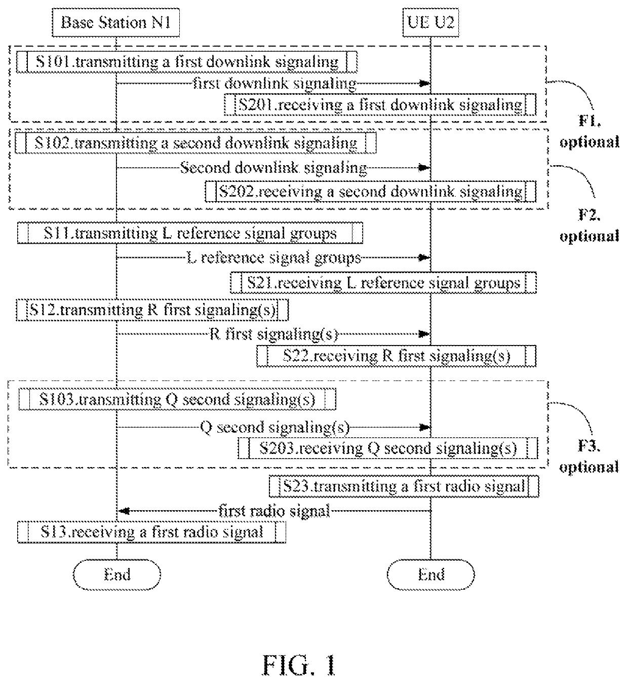
[0260]Embodiment 1 illustrates a flowchart of wireless transmission, as shown in FIG. 1. In FIG. 1, a base station N1 is a maintenance base station for a serving cell of a UE U2. In FIG. 1, steps in box F1, box F2 and box F3 are optional, respectively.

[0261]The base station N1 transmits a first downlink signaling in step S101; transmits a second downlink signaling in step S102; transmits L reference signal groups in S11; transmits R first signaling(s) in S12; transmits Q second signaling(s) in step S103; and receives a first radio signal in step S13.

[0262]The UE U2 receives a first downlink signaling in step S201; receives a second downlink signaling in step S202; receives L reference signal groups in step S21; receives R first signaling(s) in step S22; receives Q second signaling(s) in step S203; and transmits a first radio signal in step S23.

[0263]In Embodiment 1, the L reference signal groups are transmitted by L antenna port sets respectively, the R first signaling(s) is (are) r...

embodiment 2

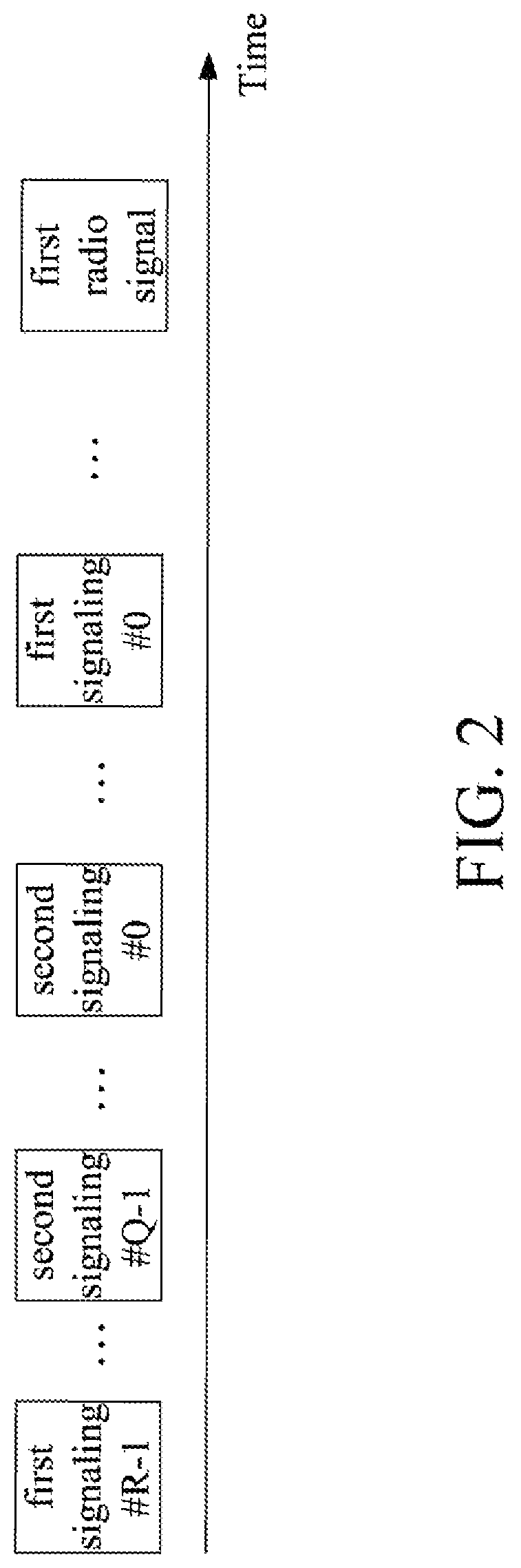
[0352]Embodiment 2 illustrates a timing diagram of R first signalings, Q second signalings and a first radio signal, as shown in FIG. 2. In FIG. 2, indices of the R first signaling(s) are #0, #1, #2 . . . , #R-1, respectively; indices of the Q second signaling(s) are #0, #1, #2 . . . , #Q-1, respectively.

[0353]In Embodiment 2, time domain resources occupied by any two first signalings of the R first signalings are orthogonal (i.e., non-overlapping); time domain resources occupied by any two first signalings of the Q second signalings are orthogonal (i.e., non-overlapping); a time domain resource occupied by the first radio signal is after a time domain resource occupied by a first signaling #0 and a time domain resource occupied by a second signaling #0.

[0354]In one embodiment, the R first signalings are dynamic signalings respectively.

[0355]In one embodiment, the R first signalings are dynamic signalings used for Uplink Grant respectively.

[0356]In one embodiment, the R first signal...

embodiment 3

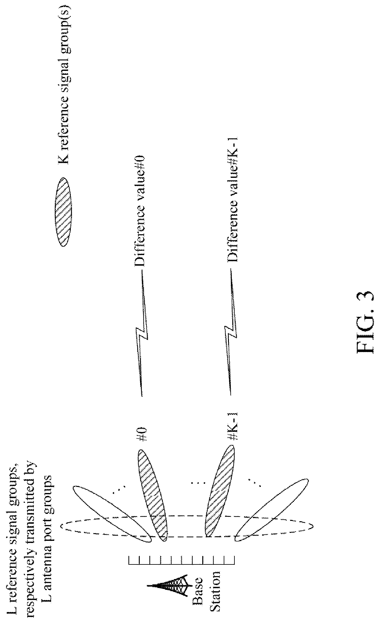
[0361]Embodiment 3 illustrates a schematic diagram of a relationship between K reference signal group(s) and K difference value(s), as shown in FIG. 3.

[0362]In Embodiment 3, L reference signal groups are transmitted by L antenna port sets respectively, the K reference signal group(s) is (are) a subset of the L reference signal groups. The K difference value(s) respectively corresponds(correspond) to K first reference power value(s). Measurement(s) on K reference signal group(s) is (are) respectively used for determining the K first reference power value(s). The L is a positive integer greater than 1, the K is a positive integer not greater than the L.

[0363]In one embodiment, the K first reference power value(s) is (are) linearly correlated to the K pathloss value(s) respectively, the K pathloss value(s) is (are) respectively determined by measurement(s) on the K reference signal group(s).

[0364]In one embodiment, a given reference signal group is one of the K reference signal group(s...


PUM


Abstract

The present disclosure discloses a method and a device used for power adjustment in a User Equipment (UE) and a base station. The UE receives L reference signal groups transmitted by L antenna port sets respectively; receives R first signaling(s) for determining R first offset(s); and then transmits a first radio signal for determining K difference value(s) corresponding to K first reference power value(s) respectively, each of which is linearly correlated to a sum of the R first offset(s). Measurement(s) on K reference signal group(s) is (are) respectively used for determining K first reference power value(s). A transmitting power of the first radio signal is a first power associated with a first reference signal group, which is one of the K reference signal group(s). All of the L antenna port sets are used for one same serving cell or carrier. The disclosure helps improve power control performance and reduce overhead.

Description

CROSS-REFERENCE TO RELATED APPLICATION[0001]This application is a continuation of International Application No. PCT / CN2018 / 071702, filed Jan. 8, 2018, claiming the priority benefit of Chinese Patent Application Serial Number 201710017344.7, filed on Jan. 10, 2017, and Chinese Patent Application Serial Number 201710045876.1, filed on Jan. 22, 2017, the full disclosure of which is incorporated herein by reference.BACKGROUNDTechnical Field[0002]The present disclosure relates to transmission methods and devices supporting power adjustment in wireless communication systems, and in particular to a transmission scheme and a device in a wireless communication system with large numbers of antennas deployed at a base station side.Related Art[0003]In existing Long Term Evolution (LTE) system, Power Headroom Reporting (PHR) is used by a base station for acquiring differences between a nominal maximum transmitting power of a User Equipment (UE) and an estimated power for transmission on a UL-SCH...

Claims


Application Information

Patent Timeline
Patent Type & Authority Patents(United States)
IPC IPC(8): H04B7/0404H04W24/10H04W36/06H04W36/16H04W36/20H04W36/30H04W52/04H04W52/24H04W52/32H04W52/36H04W52/42H04W72/04H04W80/08H04W88/02H04W88/08H04B7/0413H04B7/0426H04B7/06H04B7/08H04W24/02H04L1/00H04L1/18H04W92/10H04B7/0408
CPCH04L1/1822H04B7/0408H04L1/0026H04B7/088H04L1/1864H04L1/1819H04B7/0617H04W52/245H04W24/02H04W72/0473H04B7/0413H04L1/1896H04W52/36H04W36/06H04W36/165H04B7/0404H04W52/04H04W52/365H04L1/0004H04W36/30H04B7/0426H04W72/046H04W52/246H04W36/20H04W52/325H04W52/42H04W24/10H04W52/243H04W52/242H04W92/10H04W88/02H04W88/08H04W80/08H04B7/06
Inventor ZHANG, XIAOBO
Owner SHANGHAI LANGBO COMM TECH CO LTD
Why Eureka
Try Eureka