Strain wave gearing

a gearing and strain wave technology, applied in the direction of toothed gearings, belts/chains/gearings, toothed gearings, etc., can solve the problems of insufficient strength and transmission characteristics of strain wave gearings, and the transmission characteristics and strength characteristics are especially susceptible to effects

Active Publication Date: 2020-10-27
HARMONIC DRIVE SYST IND CO LTD
View PDF11 Cites 1 Cited by
  • Summary
  • Abstract
  • Description
  • Claims
  • Application Information

AI Technical Summary

Benefits of technology

[0006]In view of the above, an object of the present invention is to provide a strain wave gearing in which it is possible to improve a meshing state in a tooth trace direction between an externally toothed gear and an internally toothed gear.Means of Solving the Problems
[0012]a wave generator fitted inside the externally toothed gear so as to be capable of relative rotation, the wave generator causing the externally toothed gear to flex in a non-circular shape and pushing the externally toothed gear toward the internally toothed gear supported by the supporting inner peripheral surface, thereby causing the externally toothed gear to mesh with the internally toothed gear at a plurality of locations that are set apart in a circumferential direction,
[0014]In the present invention, the flexible internally toothed gear and the flexible externally toothed gear mesh with each other in an overlapping meshing state. Any difference in meshing between the two gears at tooth-trace-direction positions is mitigated. It is possible to suppress reductions in transmission characteristics and strength characteristics of the strain wave gearing caused by the effects of dimensional precision in manufacturing and precision in assembly of the components.
[0019]In the strain wave gearing of the present invention, the externally toothed gear caused to flex by the wave generator meshes with the internally toothed gear in an overlapping meshing state. The floating ring supporting the internally toothed gear from the outer peripheral side maintains the overlapping meshing state and supports the internally toothed gear in a floating state that enables displacement in a manner following a state of radial flexing in the tooth trace direction of the internal teeth of the internally toothed gear. It is possible to mitigate any difference in meshing state between the two gears at tooth-trace-direction positions. It is also possible to suppress reductions in transmission characteristics and strength characteristics of the strain wave gearing caused by the effects of dimensional precision in manufacturing and precision in assembly of the components.
[0020]The wave generator typically causes the external tooth formation portion to flex in an ellipsoidal shape and causes the external teeth to mesh with the internal teeth at positions on both major-axis-direction ends of the ellipsoidal shape. In this case, the inner diameter of the supporting inner peripheral surface of the floating ring is set on the basis of a major diameter of the outer peripheral surface of the internal tooth formation portion caused to flex in an ellipsoidal shape by the wave generator via the external tooth formation portion. Appropriately setting the inner diameter of the floating ring makes it possible to prevent increases in rotational torque of the wave generator.
[0024]Furthermore, it is desirable to provide an elastic body that restricts movement of the floating ring in the axial direction.

Problems solved by technology

Due to this meshing, transmission characteristics and strength characteristics of the strain wave gearing are especially susceptible to effects of dimensional precision in manufacturing and precision in assembly of the components.
However, these are not sufficient.

Method used


Image

  • Strain wave gearing
  • Strain wave gearing
  • Strain wave gearing

Examples


Embodiment Construction

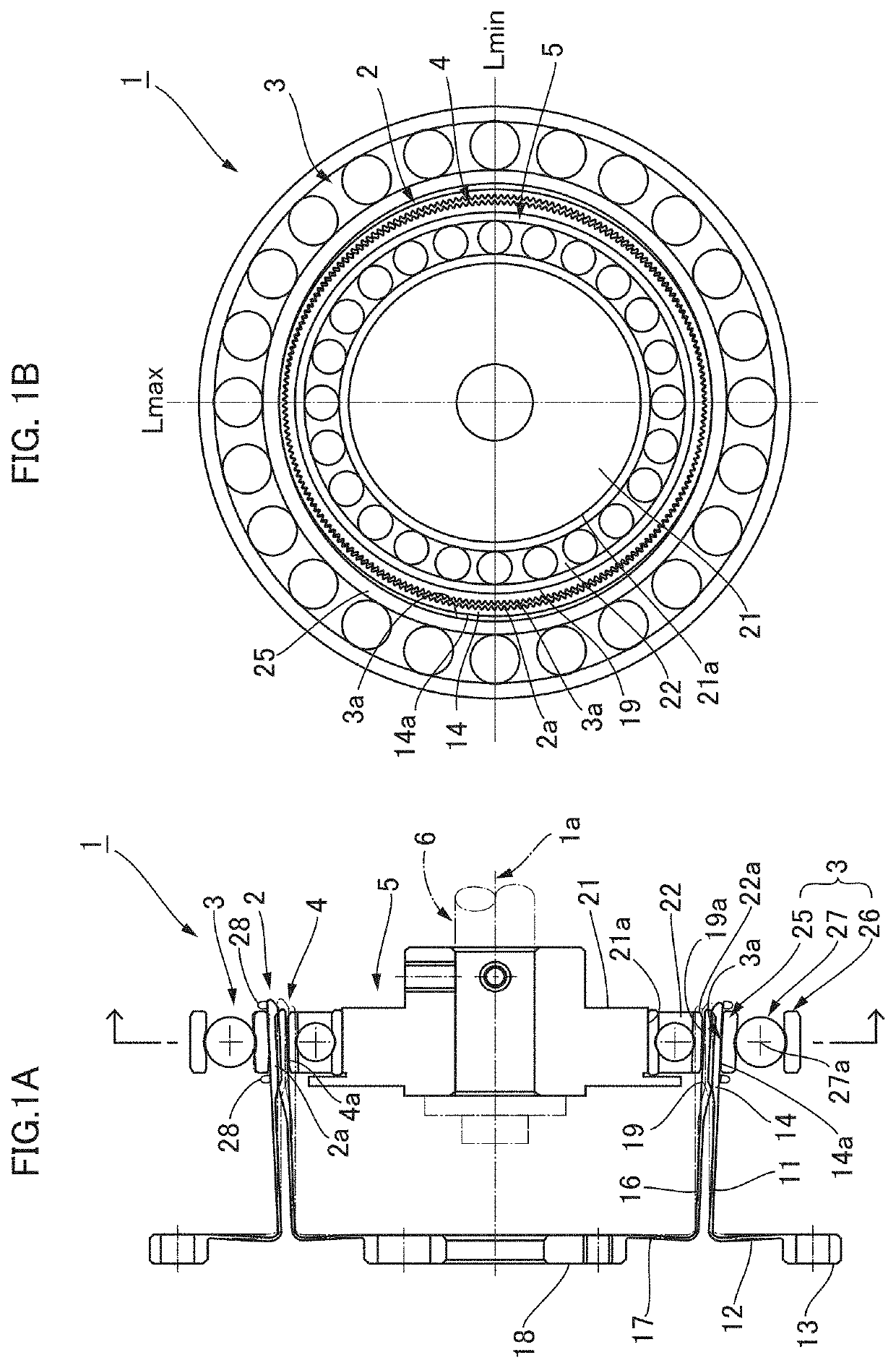
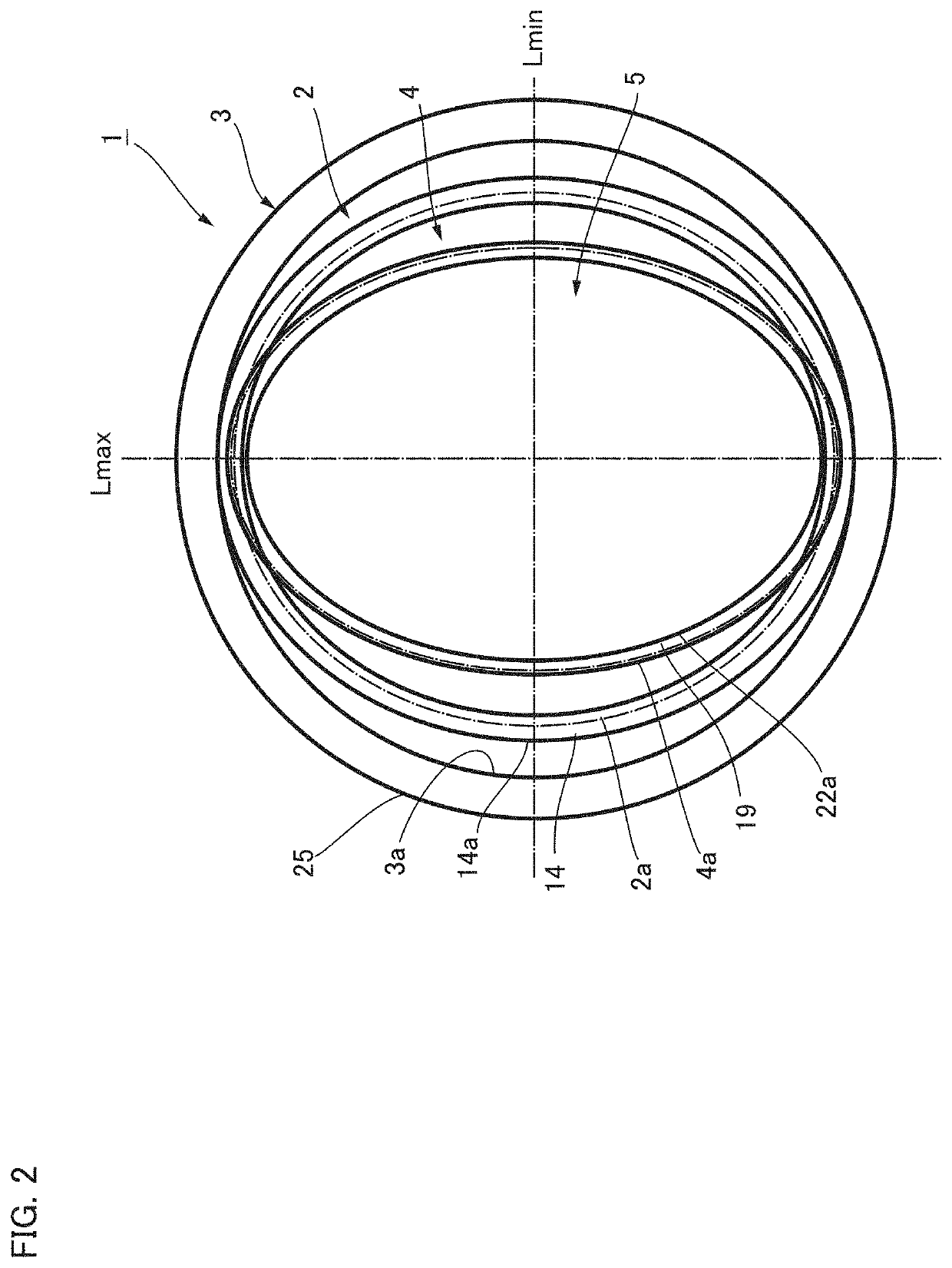
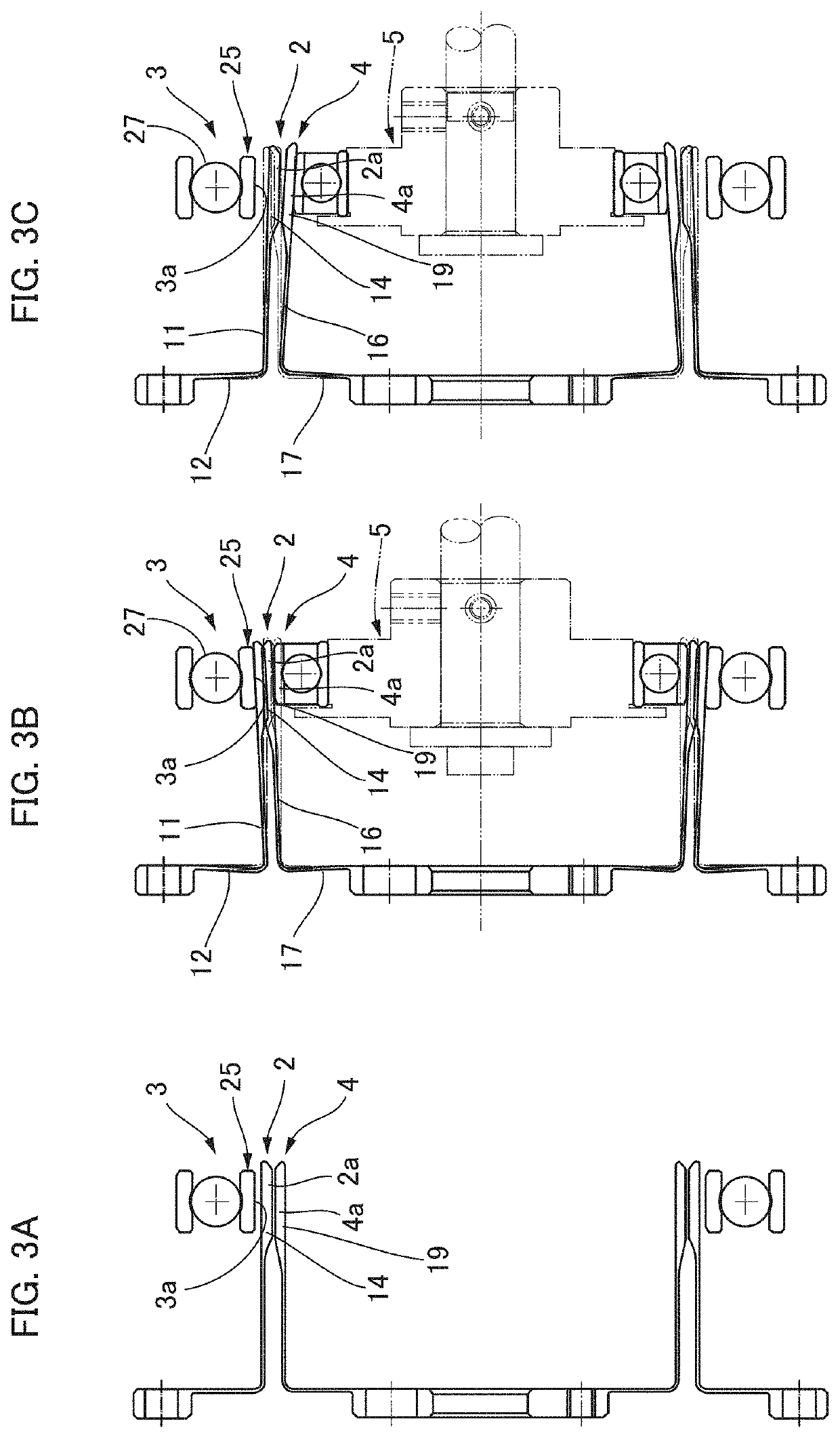
[0035]Embodiments of a strain wave gearing to which the present invention is applied are described below with reference to the accompanying drawings. FIG. 1A is a schematic longitudinal cross-sectional view of a strain wave gearing according to an embodiment, and FIG. 1B is a schematic transverse cross-sectional view of the strain wave gearing. FIG. 2 is a diagram in which a state of flexing of the components of the strain wave gearing is exaggerated. The strain wave gearing 1 is provided with a flexible internally toothed gear 2 capable of flexing in a radial direction, a support mechanism 3 provided with a circular supporting inner peripheral surface 3a for supporting the internally toothed gear 2 from an outer peripheral side, a flexible externally toothed gear 4 disposed concentrically inside the internally toothed gear 2, and a wave generator 5.

[0036]The wave generator 5 is fitted inside the externally toothed gear 4 so as to be capable of relative rotation, the wave generator ...


PUM


Abstract

In a strain wave gearing, a flexible externally toothed gear flexed by a wave generator meshes with a flexible internally toothed gear while in an overlapping meshing state. A floating ring, which supports the internally toothed gear from the outer circumferential side, maintains the overlapping state of the meshing and supports the internally toothed gear in a floating state that allows displacement following a state of radial flexion in the tooth trace direction of the internal teeth of the internally toothed gear. Differences between the meshing states of both gears can be alleviated at each position in the tooth trace direction. Degradation in the transmission characteristics and the strength characteristics of the strain wave gearing caused by manufacturing dimensional accuracy of each component and assembly accuracy can be suppressed.

Description

TECHNICAL FIELD[0001]The present invention relates to a strain wave gearing, and in particular relates to a strain wave gearing provided with a flexible internally toothed gear and a flexible externally toothed gear.BACKGROUND ART[0002]Typically, in strain wave gearings used as reducers, etc., a flexible externally toothed gear is disposed inside a rigid internally toothed gear, and the externally toothed gear is caused to flex in an ellipsoidal shape by a wave generator and to mesh with the internally toothed gear. When the wave generator is caused to rotate by a motor, etc., meshing positions of the two gears move along a circumferential direction. As a result, relative rotation is produced between the two gears, the relative rotation being reduced by a prescribed reduction ratio that corresponds to a difference in the number of teeth of the two gears. One of the gears is secured so as not to rotate, whereby reduced rotation is derived from the other gear.[0003]In a cup-shaped or ...

Claims


Application Information

Patent Timeline
Patent Type & Authority Patents(United States)
IPC IPC(8): F16H33/00F16H49/00F16H35/00F16H37/00
CPCF16H49/001F16H2049/003F16H1/32
Inventor KOBAYASHI, MASARUMARUYAMA, AKIRA
Owner HARMONIC DRIVE SYST IND CO LTD
Why Eureka
Try Eureka