
Determination of RPM from vibration spectral plots

a technology of vibration spectral plots and rpm, which is applied in the direction of measuring devices, devices using electric/magnetic means, instruments, etc., can solve the problems of accelerating wear and other damage to equipment, affecting and loosing balance or alignment of rotating equipment with time, so as to improve the accuracy of assumed rotational speed

Active Publication Date: 2020-11-03
COMPUTATIONAL SYST
View PDF9 Cites 0 Cited by
  • Summary
  • Abstract
  • Description
  • Claims
  • Application Information

AI Technical Summary

Benefits of technology

[0022]Accordingly, by using the apparatus described herein a user may be able to either improve the accuracy of the assumed rotational speed by scanning across the vibrational spectral peaks or, if this does not reflect a reasonable rotational speed, then to scan across all the spectral peaks to determine the most likely rotational speed.

Problems solved by technology

Rotating equipment, such as fans, motors, turbines, and the like, tend to lose their balance or alignment with time due to conditions such as wear, varying load, damage, misuse, and foreign matter accumulation.
As balance and alignment are lost, the equipment produces excessive vibration, which if left uncorrected, causes accelerated wear and other damage to the equipment.
However, the rotational speed is not often known at the time of data collection.
As another example, a defective anti-friction bearing produces vibration that has a fixed, but non-integer relationship to the speed of the shaft.
Again, without knowledge of the speed of the shaft, the defective bearing is more difficult to diagnose.
Further, in a piece of rotary equipment such as a gear box, which may have several gears of different sizes, a problem such as a cracked tooth on one of the gears creates vibration that is synchronous with the rotational speed of a shaft.
The problem is that without use of a tachometer to measure the rotational speed it is difficult to determine the rotational speed accurately.
Thus the assumed rotational speed may be completely incorrect due to manual data entry errors.

Method used


Image

  • Determination of RPM from vibration spectral plots
  • Determination of RPM from vibration spectral plots
  • Determination of RPM from vibration spectral plots

Examples


Embodiment Construction

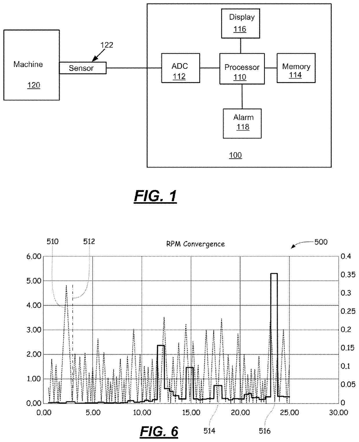
[0031]The above and other needs are met by an apparatus for use in determining the rotational speed of a machine, such as a shaft of a pump, motor, turbine, compressor, gear box, and the like using vibrational data. Such apparatus, as described in more detail below, may be used in the absence of a tachometer or nameplate information about the rotational speed of the machine.

[0032]Vibration analyzers are useful to sense, analyze, and record vibration in rotating equipment, which vibration can, if left uncorrected, degrade the efficiency of, or even destroy the rotating equipment. Preferably, a portable or hand-held analyzer is used to collect and analyze vibration data, which may also be uploaded and stored in a base computer for further analysis. Aspects of the invention are not limited to portable or hand-held vibration analyzers, as continuous or on-line analyzers may also be used to collect vibration data as well as vibration analysis software programs used in post-acquisition an...


PUM


Abstract

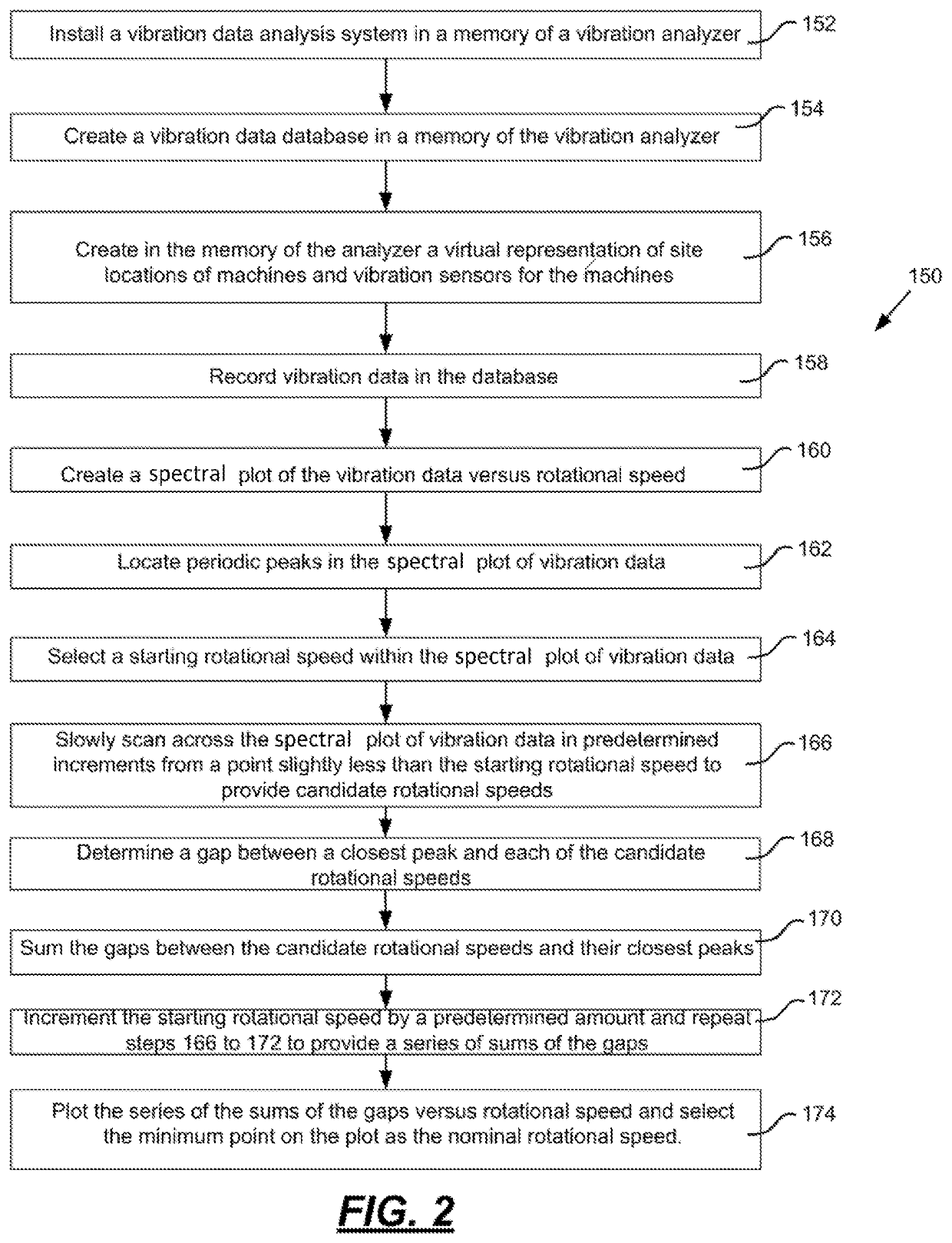
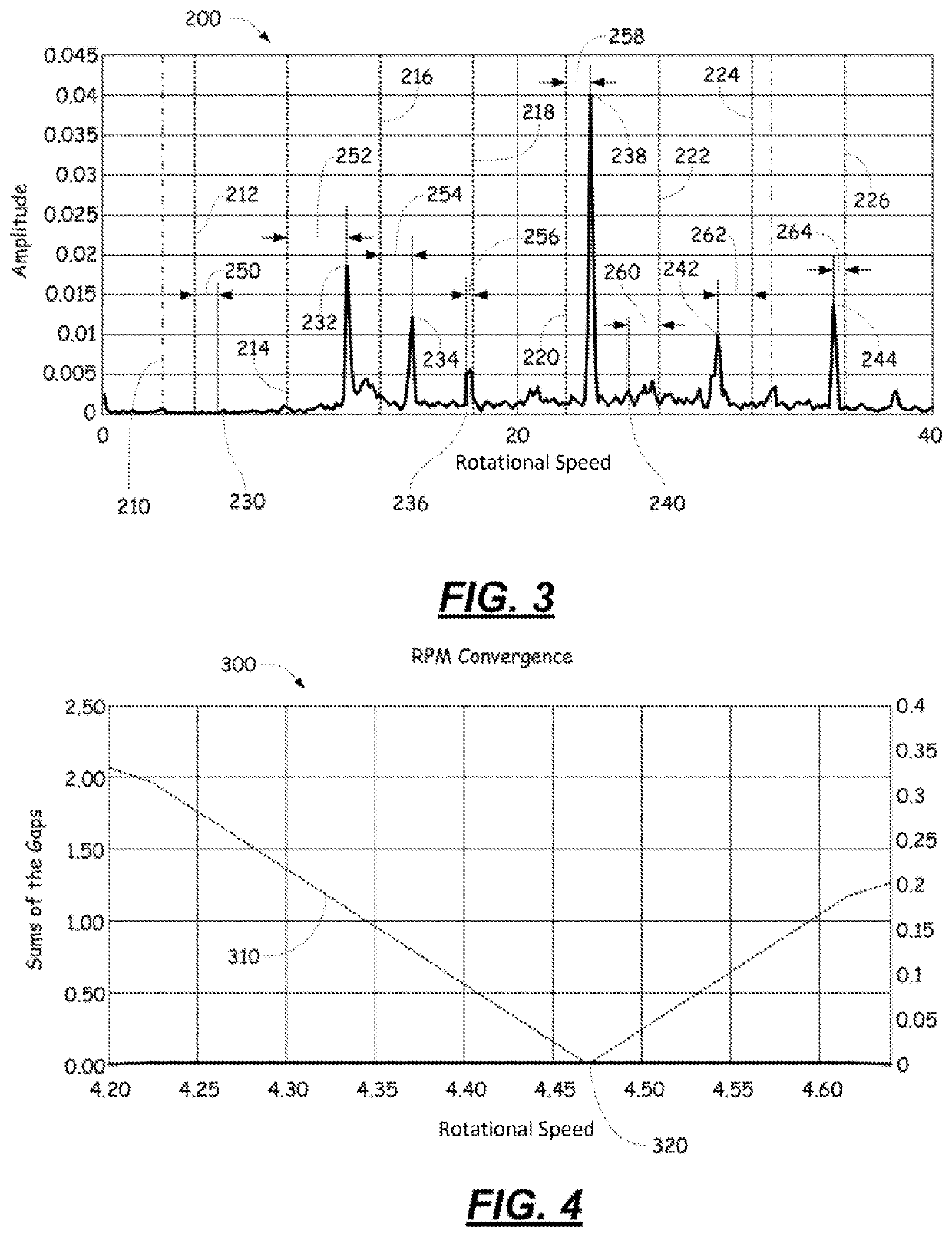
A vibration analyzer for use in determining a rotational speed. The vibration analyzer includes: a) an input for sensing vibration data, b) a memory for storing the vibrational data, and c) a processor. The processor 1) produces a spectral plot of the vibrational data, 2) locates peaks in the spectral plot, 3) inputs a rotational speed, and 4) scans the spectral plot in predetermined rotational speed increments to provide a candidate rotational speeds. For each candidate rotational speed i) a number of associated harmonics is identified, ii) closest peaks in the spectral plot to the candidate rotational speed and its harmonics are located, iii) gaps between the closest peaks and the candidate rotational speed and its harmonics are measured, iv) summed, and a sum of the gaps is recorded. In step (5) The candidate rotational speed that is associated with a minimum sum is selected as the nominal rotational speed.

Description

TECHNICAL FIELD[0001]The disclosure relates to the apparatus for the determination of rotational speed for a machine, and more particularly to analytical instruments for determining rotational speed using vibration analysis in the absence of actual rotational speed measurements.BACKGROUND OF THE INVENTION[0002]Rotating equipment, such as fans, motors, turbines, and the like, tend to lose their balance or alignment with time due to conditions such as wear, varying load, damage, misuse, and foreign matter accumulation. As balance and alignment are lost, the equipment produces excessive vibration, which if left uncorrected, causes accelerated wear and other damage to the equipment.[0003]Vibration analyzers detect the vibration emitted from rotating equipment. Such analyzers determine the source of the vibration, whether it be imbalance, misalignment, worn bearings, missing or broken parts, or some other problem. To make a proper diagnosis of the vibration problem, the rotational speed ...

Claims


Application Information

Patent Timeline
Patent Type & Authority Patents(United States)
IPC IPC(8): G01P3/48
CPCG01P3/4802G01P3/02G01P3/48
Inventor HAYZEN, ANTHONY J.BOWERS, III, STEWART V.
Owner COMPUTATIONAL SYST
Learn More