
Method for performing single-stage cranioplasty reconstruction with a clear custom cranial implant

a cranial implant and single-stage technology, applied in the field of surgery, can solve the problems that the procedure cannot be performed in the setting of a standard, and achieve the effects of increasing the risk of resulting deformity, increasing complexity and artistic demand, and exponentially increasing difficulty

Active Publication Date: 2020-11-17
LONGEVITI NEURO SOLUTIONS LLC
View PDF35 Cites 3 Cited by
  • Summary
  • Abstract
  • Description
  • Claims
  • Application Information

AI Technical Summary

Benefits of technology

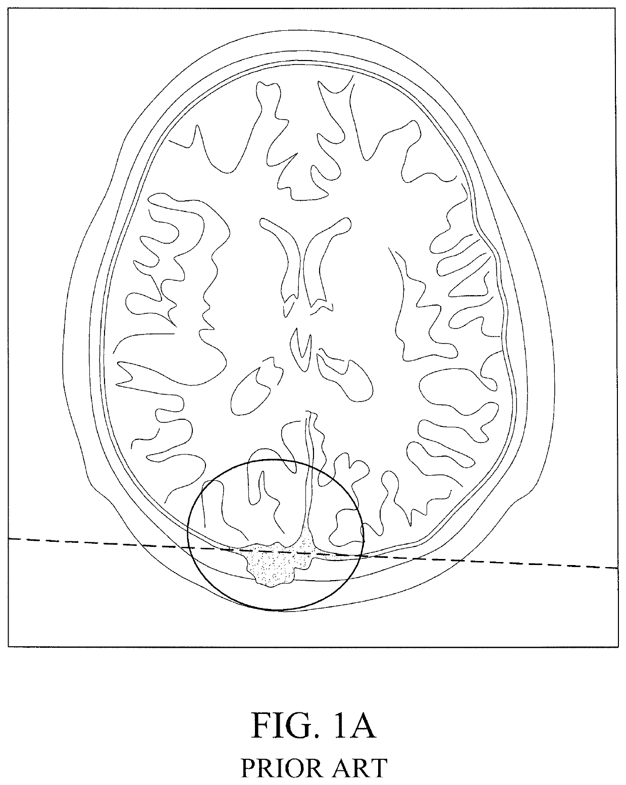
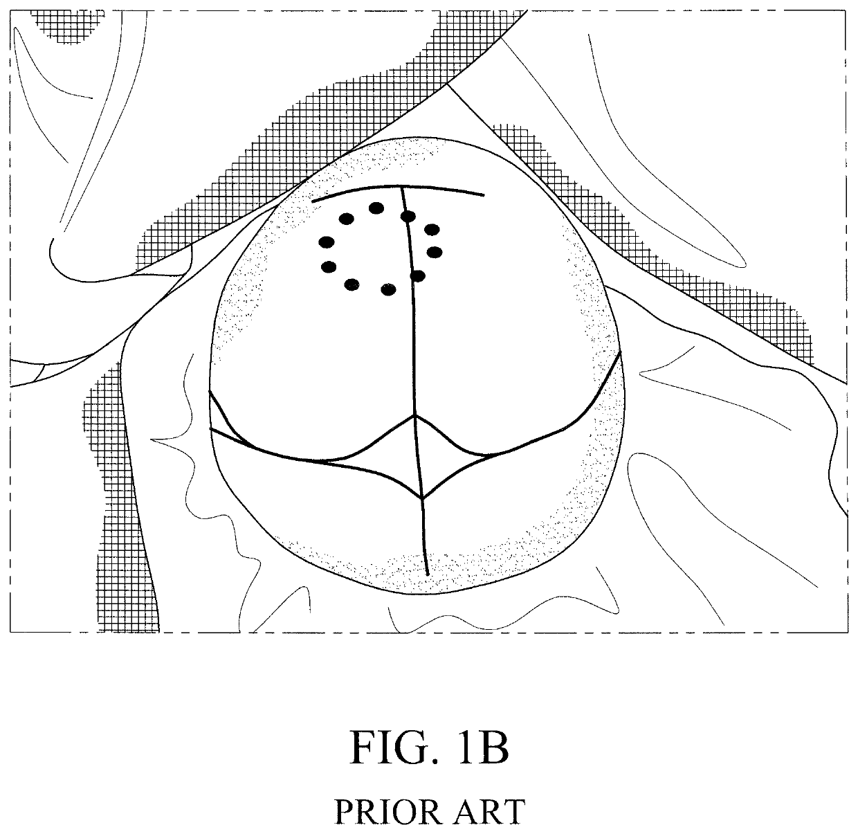
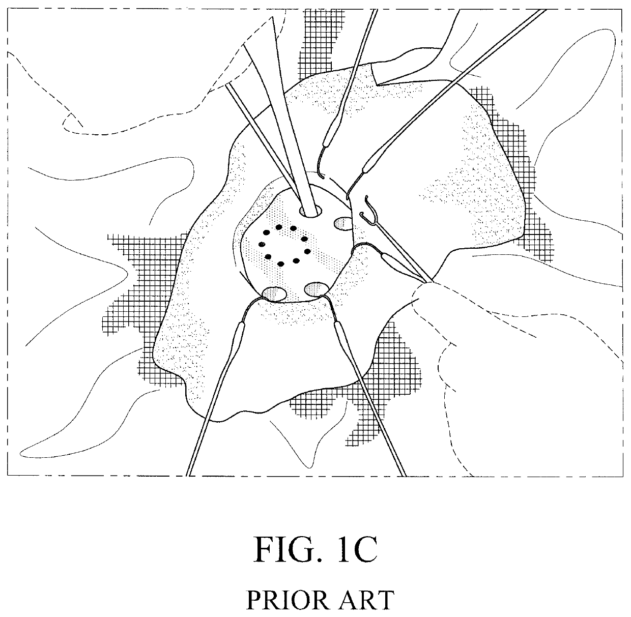
[0013]It is, therefore, an object of the present invention to provide a method for cranioplasty. The method includes first prefabricating a clear craniofacial implant with complete transparency and clarity based upon information generated by preoperative scans. The method also includes creating a cranial, craniofacial, and / or facial defect, and positioning the clear craniofacial implant over the cranial, craniofacial, and / or facial defect. Thereafter, cut lines are traced by hand on the clear craniofacial implant (since one can see the bony edges of the cranial, craniofacial and / or facial defect through the clear craniofacial implant) as it lies over the cranial, craniofacial, and / or facial defect, wherein a boundary of the cranial, craniofacial, and / or facial defect is easily viewable through the clear craniofacial implant as a result of the clear construction of the craniofacial implant. The clear custom craniofacial implant is cut along the traced cut lines drawn by hand for optimal fit of the craniofacial implant along the cranial, craniofacial, and / or facial defect and to create a final clear craniofacial implant with exact fit. The final clear craniofacial implant is attached to the cranial, craniofacial, and / or facial defect. This procedure would not be possible in the setting of a standard, “opaque” implant.
[0030]It is a further object of the present invention to provide a method for cranioplasty wherein a neurological device is incorporated within the clear craniofacial implant in an effort to reduce visible deformity and / or pressure on the scalp risking extrusion.

Problems solved by technology

This procedure would not be possible in the setting of a standard, “opaque” implant.

Method used


Image

  • Method for performing single-stage cranioplasty reconstruction with a clear custom cranial implant
  • Method for performing single-stage cranioplasty reconstruction with a clear custom cranial implant
  • Method for performing single-stage cranioplasty reconstruction with a clear custom cranial implant

Examples


Embodiment Construction

[0046]The detailed embodiments of the present invention are disclosed herein. It should be understood, however, that the disclosed embodiments are merely exemplary of the invention, which may be embodied in various forms. Therefore, the details disclosed herein are not to be interpreted as limiting, but merely as a basis for teaching one skilled in the art how to make and / or use the invention.

[0047]Referring to FIGS. 2A-2F, 3A, 3B, and 4, the present invention relates to a novel method for performing single-stage cranioplasty with “clear” customized implants (see for example, FIGS. 2C and 2D showing the clear custom craniofacial implant 10 held directly above a skull tumor defect following extirpation (that is, the cranial, craniofacial, and / or facial defect 100 as discussed below) prior to single-stage modification). As explained above in the Background of the Invention, the method of “single-stage cranioplasty” is defined as a surgery where the surgeon intends to create a complica...


PUM


Abstract

A method for single-stage cranioplasty reconstruction includes prefabricating a clear craniofacial implant, creating a cranial, craniofacial, and / or facial defect, positioning the clear craniofacial implant over the cranial, craniofacial, and / or facial defect, tracing cut lines on the clear craniofacial implant as it lies over the cranial, craniofacial, and / or facial defect, cutting the prefabricated clear custom craniofacial implant along the hand-marked lines for optimal fit of the clear implant within the cranial, craniofacial, and / or facial defect, and attaching the final clear craniofacial implant to the cranial, craniofacial, and / or facial defect with standard fixation methods of today.

Description

CROSS REFERENCE TO RELATED APPLICATION[0001]This application claims the benefit of U.S. Provisional Patent Application Ser. No. 62 / 489,036, filed Apr. 24, 2017, entitled “METHOD FOR PERFORMING SINGLE-STAGE CRANIOPLASTY RECONSTRUCTION WITH A CLEAR CUSTOM CRANIAL IMPLANT.”BACKGROUND OF THE INVENTION1. Field of the Invention[0002]The present invention generally relates to the field of surgery. In particular, the invention relates to the brain and skull, the art of reconstructing skull defects (i.e., cranioplasty), neurosurgery, neurology, neuroplastic and reconstructive surgery, and craniofacial plastic surgery.2. Description of the Related Art[0003]Craniectomies requiring skull reconstruction (i.e., cranioplasty) are often indicated for a multitude of etiologies including decompression (i.e., skull removal) following stroke or traumatic brain injury, bone flap infection (i.e., osteomyelitis) and / or bone flap resorption following previous neurosurgery, and / or oncological ablation for m...

Claims


Application Information

Patent Timeline
Patent Type & Authority Patents(United States)
IPC IPC(8): A61F2/28A61B17/68A61B17/16A61B17/80A61B34/10A61F2/30
CPCA61B17/688A61B34/10A61F2/2875A61B17/8085A61B2034/108A61F2002/30617A61F2/30942A61F2002/30948A61B2034/105A61F2002/3096A61F2002/2882A61F2240/002A61F2002/3009
Inventor GORDON, CHAD R.CHRISTOPHER, JESSERABINOVITZ, BRADLEY
Owner LONGEVITI NEURO SOLUTIONS LLC
Learn More