Apparatus, method and system for manufactured structures

a manufactured structure and apparatus technology, applied in the direction of manufacturing tools, packaging, and so on, can solve the problems of carbon fiber composites being easily attacked, expensive to manufacture and difficult to repair, and difficult to recycle or re-use, so as to reduce the effective height of the tab with respect to the skin or other components, the effect of lowering the wings

Active Publication Date: 2020-11-17
PIASECKI AIRCRAFT CORP
View PDF19 Cites 3 Cited by
  • Summary
  • Abstract
  • Description
  • Claims
  • Application Information

AI Technical Summary

Benefits of technology

[0013]Each of the strips may be equipped with a plurality of tabs at the edge of the strips. The skin may be equipped with slots corresponding to the tabs, so that the tabs may be inserted into the slots when the strips and skin are assembled. Twisting or bending the tabs when the tabs are inserted into the slots will maintain the strips and skin in engagement during the brazing process, avoiding the need for fixturing in the vacuum-brazing oven.
[0082]The tabs may be configured to have wings on either side of the tab. The wings define flat springs. When the tab is inserted through a slot in a skin or other component and is twisted with respect to the skin or other component, the effective height of the tab with respect to the skin or other component is reduced, which lowers the wings and bring the wings into contact with the surface of the skin or other component on either side of the slot. The wings bear upon the skin or other component and elastically deform. The wings apply a force to the skin or other component that is determined by the spring rate of the flat springs defined by the wings and by the elastic deformation of the wings. The wings allow the pressure exerted by the tab on the skin or other component to be controlled and allows damage to the skin by the tab when the tab is twisted to be reduced or eliminated.S. Sheet Skin Supported by a Rib Lattice and Individual Tiles

Problems solved by technology

Carbon fiber composite structures can be stiff, strong and light; however, carbon fiber composites are expensive to manufacture and difficult to repair.
Carbon fiber composites are also subject to attack by solvents, are flammable, and are difficult to recycle or re-use.

Method used


Image

  • Apparatus, method and system for manufactured structures
  • Apparatus, method and system for manufactured structures
  • Apparatus, method and system for manufactured structures

Examples


Embodiment Construction

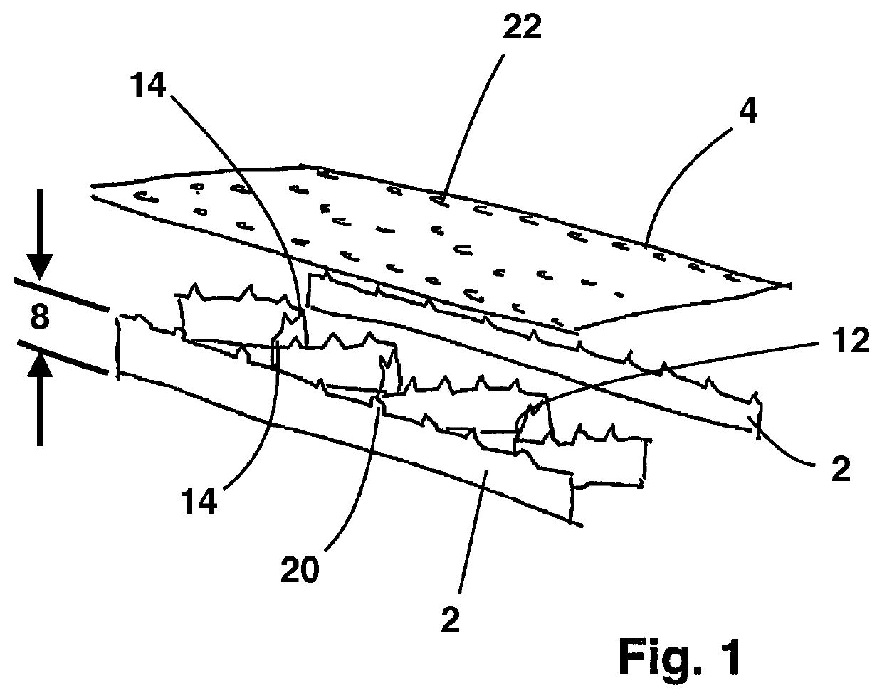
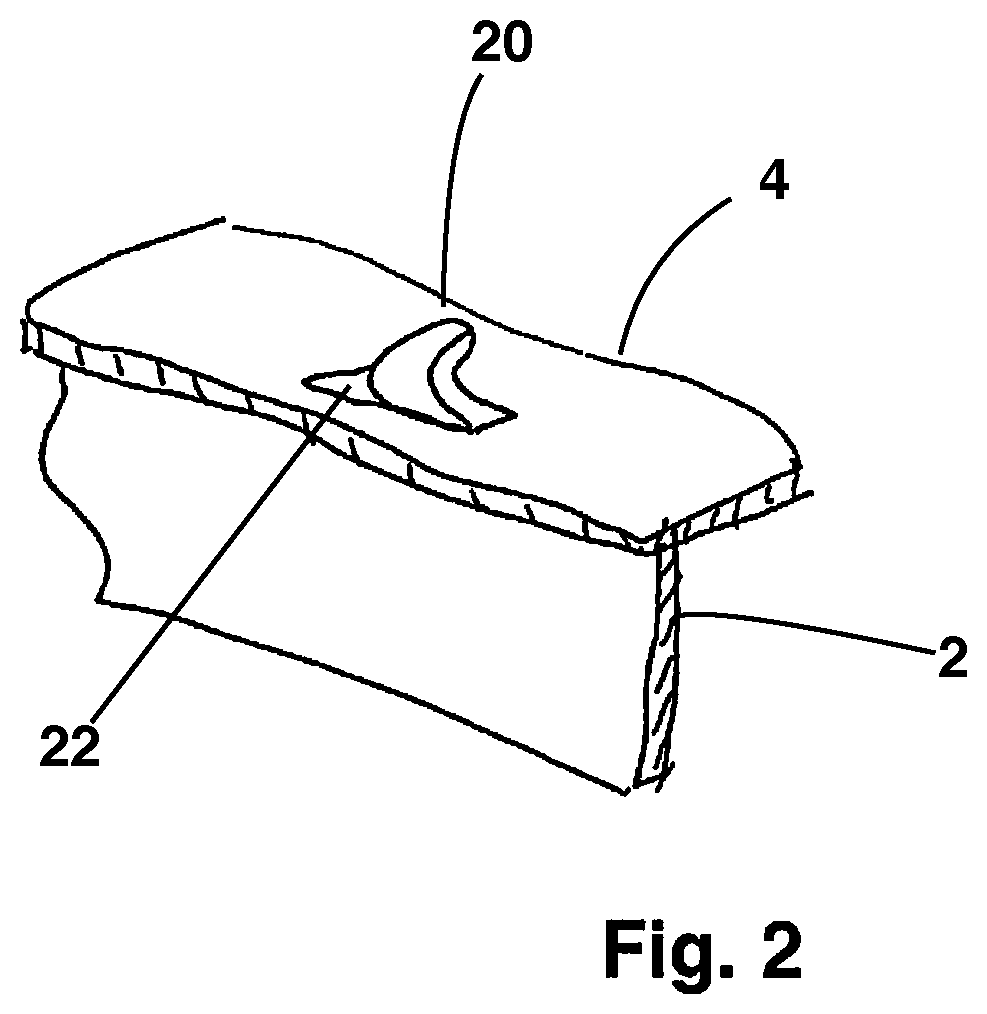
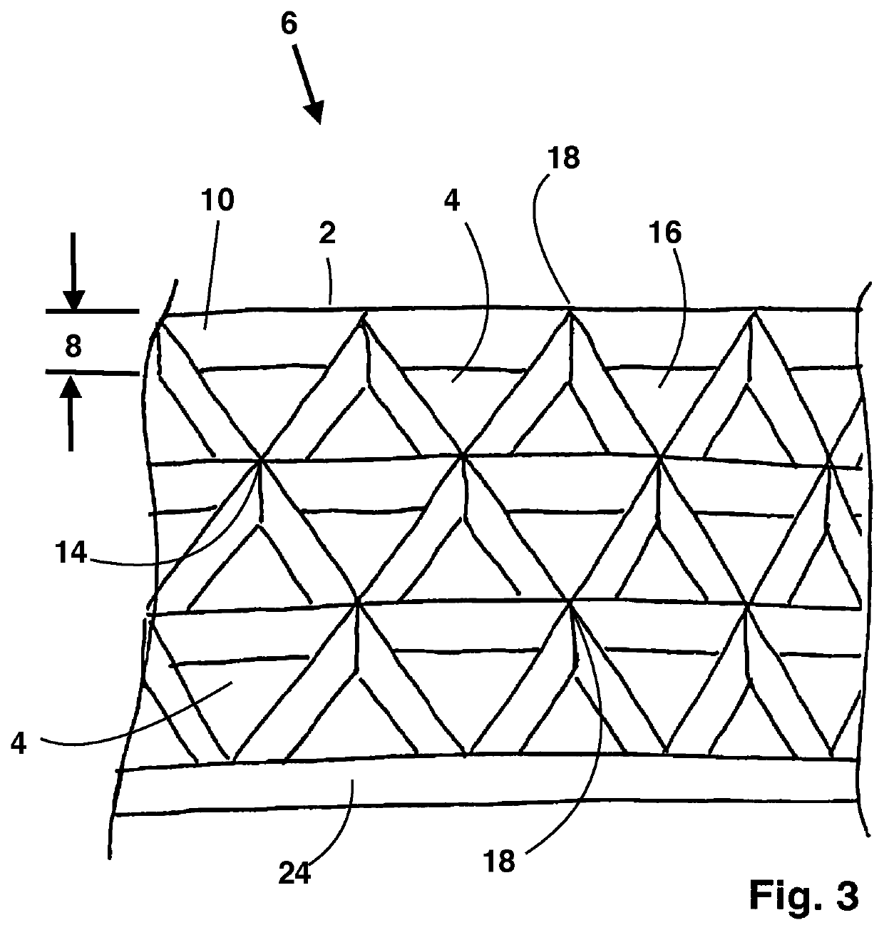
[0120]FIGS. 1, 2 and 3 illustrate the first invention in which metallic strips 2 of thin-section stainless steel are vacuum-brazed to thin stainless steel skin 4 to define an isogrid structure 6. The strips 2 of thin-section stainless steel sheet are long compared to their width 8. The width 8 of each strip 2 defines the depth of a rib 10 of a completed structure 24. In a vacuum-brazing oven, strips 2 that are bent at intervals to define angles 12 along the length of the strips 2 are interspersed with strips 2 that are not bent to define angles 12 along the length of the strips 2. Each apex 14 of each angle 12 defined by each bent strip 2 is placed in contact with a side of an un-bent strip 2 to define one or more triangles 16. The bent strips 2, unbent strips 2 and skin are brazed together in a vacuum-brazing oven.

[0121]For unbent strips 2 that have a bent strip 2 on either side, the apex 14 of each bent strip 2 is located at corresponding locations on opposite, corresponding sides...


PUM

PropertyMeasurementUnit
metallic structureaaaaaaaaaa
perimeteraaaaaaaaaa
volumesaaaaaaaaaa

Abstract

A metallic structure defines ribs and a skin supported by the ribs. The ribs may be defined by metal strips and the skin may be attached to the ribs. Alternatively, the skin may be defined by a plurality of tiles and the ribs may be defined by flanges of each of the plurality of tiles that cooperate to define the ribs. Tiles may be attached to separate rib lattice. Structurally weak locations at nodes where ribs intersect may be reinforced. The components may be brazed together and the stiffness of adjacent locations in the structure adjusted in the brazing operation to reduce the difference in stiffness and to reduce resulting stress risers. The metallic structure may be armored using metal foam to absorb the energy of a projectile.

Description

I. STATEMENT OF RELATED APPLICATIONS[0001]This application is entitled to priority to U.S. Provisional Patent Application 62 / 417,428 filed Nov. 4, 2016, which is incorporated by reference as if set forth in full herein.II. BACKGROUND OF THE INVENTIONA. Field of the Invention[0002]The Invention relates to the construction of structures and has particular application to lightweight metallic structures such as aircraft or components of aircraft. The Invention includes apparatus, methods and systems for manufacturing the structures, for using the structures, for monitoring the completed structures, and for adjusting the mechanical properties of the materials from which the structures are composed during the manufacturing process.[0003]One application of the Invention is in the construction of an aircraft floor that is stiff, strong, light, and more resistant to damage than prior art aircraft flooring. The Inventions is not limited to the construction of aircraft flooring and can be used...

Claims


Application Information

Patent Timeline
Patent Type & Authority Patents(United States)
IPC IPC(8): B23K1/00B23K35/30B64C1/18B23K35/36B23K1/19B23K101/02B23K103/04
CPCB23K35/3606B23K1/0014B23K35/3033B23K1/19B23K2103/05B23K2101/02B64C1/18B23K1/0008B23K1/008B64C1/062B64C2001/0072B64C2001/0081B64D37/04B64D37/08Y02T50/40
Inventor KOVNAT, SETHCHOUINARD, MICHAEL
Owner PIASECKI AIRCRAFT CORP
Why Eureka
Try Eureka