Compressor rotor blade, compressor, and method for profiling the compressor rotor blade

a compressor and rotor blade technology, applied in the direction of non-positive displacement fluid engines, non-positive displacement pumps, pump components, etc., can solve the problems of reducing and achieve the effect of increasing the degree of efficiency of the compressor

Active Publication Date: 2020-11-17
SIEMENS ENERGY GLOBAL GMBH & CO KG
View PDF19 Cites 0 Cited by
  • Summary
  • Abstract
  • Description
  • Claims
  • Application Information

AI Technical Summary

Benefits of technology

[0005]It is therefore an object of the invention to provide a compressor rotor blade, a compressor having the compressor rotor blade, and a method for profiling the compressor rotor blade, by way of which an increase in the degree of efficiency of the compressor which has the compressor rotor blade can be achieved.
[0008]It has been found that the compressor having the compressor rotor blade according to the invention and / or having the compressor rotor blade which is profiled by way of the method according to the invention has a higher degree of efficiency in the case of an at least identical operating range than a compressor having the conventional compressor rotor blade. In addition, the Mach numbers on the suction side of the compressor rotor blade according to the invention upstream of the compression shock are lower than on the suction side of the conventional compressor rotor blade. In this way, shedding of the flow on the suction side of the compressor rotor blade according to the invention is less probable than in the case of the conventional compressor rotor blade. In addition, the compressor rotor blade according to the invention can be configured with a shorter length of its profile chord than is the case in the conventional compressor rotor blade, without losses in the degree of efficiency or a reduction of the working range being accepted as a result.
[0009]It is advantageous that the curvature progression multiplied by the length of the profile chord has a maximum value which is from 2 to 4 in the convex suction side region, and the curvature progression multiplied by the length of the profile chord has a maximum value which is from 1.5 to 2.5 in the concave pressure side region.
[0010]It is advantageous that the point of the concave suction side region with the minimum curvature in the case of a perpendicular projection onto the profile chord of the profile section defines a projection point on said profile chord, which projection point is spaced apart from the front edge of the profile section by from 40% to 80%, in particular from 60% to 75%, of the length of the profile chord. It is advantageous that the point of the convex suction side region with the maximum curvature in the case of a perpendicular projection onto the profile chord of the profile section defines a projection point on said profile chord, which projection point is spaced apart from the front edge of the profile section by from 70% to 95%, in particular from 80% to 90%, of the length of the profile chord. The degree of efficiency of the compressor can be increased further by way of each of said measures.
[0011]It is advantageous that the thickness of the profile section at all points of the profile section perpendicularly with respect to the profile chord is shorter than 2.5% of the length of the profile chord.
[0015]It is advantageous that the profile section is changed in such a way that the progression of the curvature has a maximum value in the convex suction side region, which maximum value is greater than the maximum value of the progression of the curvature in the corresponding region of the conventional compressor rotor blade. The profile section is advantageously changed in such a way that the progression of the curvature multiplied by the length of the profile chord has a maximum value which is from 2 to 4 in the convex suction side region, and the progression of the curvature multiplied by the length of the profile chord has a maximum value which is from 1.5 to 2.5 in the concave pressure side region. It is advantageous that the rotor blade row is designed in such a way that it has a maximum isentropic Mach number of 1.4, in particular of at most 1.3, in the case of the nominal operating conditions. It is advantageous that the profile section is changed in such a way that the point of the concave suction side region with the minimum curvature in the case of a perpendicular projection onto the profile chord of the profile section defines a projection point on said profile chord, which projection point is spaced apart from the front edge of the profile section by from 40% to 80% of the length of the profile chord. The degree of efficiency of the compressor can be increased further by way of each of said measures.

Problems solved by technology

The losses bring about a reduction in the degree of efficiency of the compressor.

Method used


Image

  • Compressor rotor blade, compressor, and method for profiling the compressor rotor blade
  • Compressor rotor blade, compressor, and method for profiling the compressor rotor blade
  • Compressor rotor blade, compressor, and method for profiling the compressor rotor blade

Examples


Embodiment Construction

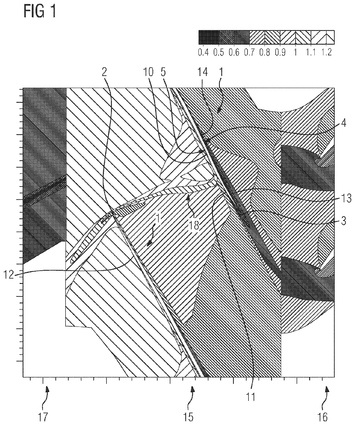
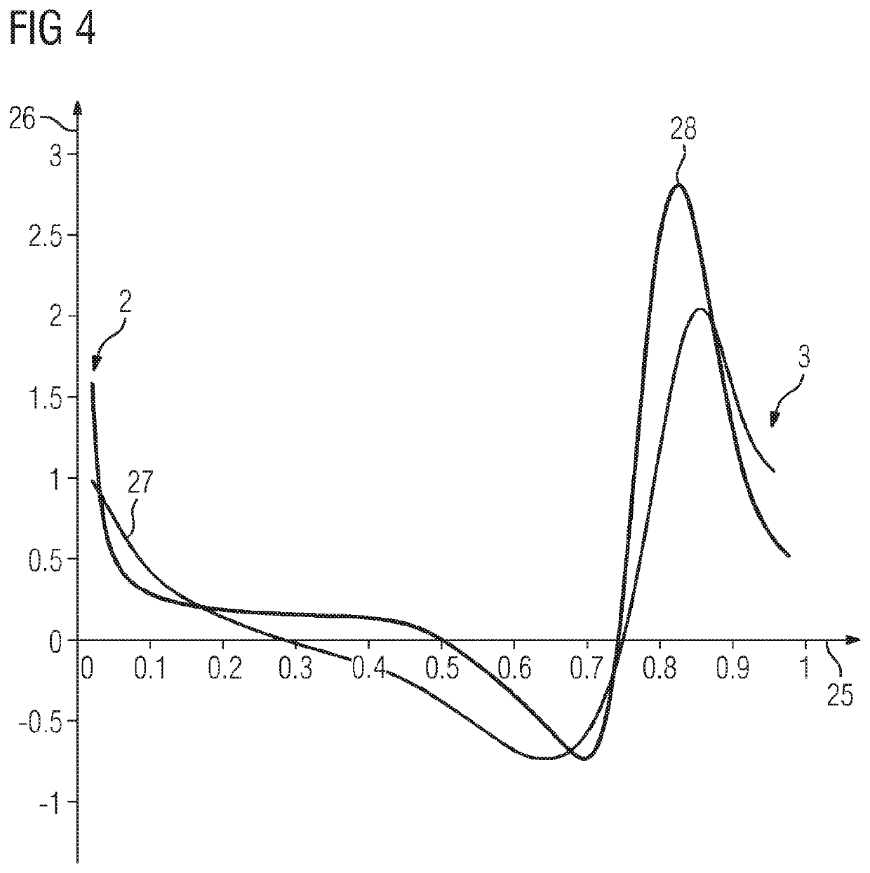
[0022]As can be seen from FIGS. 1 and 3, a compressor rotor blade 1 for a compressor of axial design has a blade profile. The blade profile has a radially inner subsonic section and a radially outer transonic section, only the transonic section being shown in FIGS. 1 and 3. The blade profile has a profile section 21 which extends in the transonic section. For example, the profile section 21 lies on a cylindrical surface, the axis of which coincides with the axis of the compressor, on a conical surface, the axis of which coincides with the axis of the compressor, on an S1 flow surface of the compressor, or in a tangential plane of the compressor.

[0023]The profile section 21 has a front edge 2, a rear edge 3, a pressure side 4 and a suction side 5. In FIG. 3, a profile chord 22 is illustrated, in addition, which profile chord 22 extends as a straight line from the front edge 2 as far as the rear edge 3. Furthermore, FIG. 3 shows a camber line 23 which extends from the front edge 2 as ...


PUM


Abstract

A compressor rotor blade for an axial-type compressor has a blade profile having a transonic section and a profile section which extends in the transonic section and has concave and convex suction-side regions on the suction side, the convex suction-side region arranged downstream of the concave suction-side region, and has convex and concave pressure-side regions on the pressure side, the concave pressure-side region arranged downstream of the convex pressure-side region. Curvature progressions on the pressure side and on the suction side are both applied in a continuous manner over a profile chord of the profile section, the positions of the minimum values of the curvature progressions deviate from each other by not more than 10% of the length of the profile chord, and the positions of the maximum values of the curvature progressions deviate from each other by not more than 10% of the length of the profile chord.

Description

CROSS REFERENCE TO RELATED APPLICATIONS[0001]This application is the US National Stage of International Application No. PCT / EP2017 / 050453 filed Jan. 11, 2017, and claims the benefit thereof. The International Application claims the benefit of European Application No. EP16155063 filed Feb. 10, 2016. All of the applications are incorporated by reference herein in their entirety.FIELD OF INVENTION[0002]The invention relates to a compressor rotor blade and to a method for profiling the compressor rotor blade.BACKGROUND OF INVENTION[0003]A compressor of axial design has at least one rotor blade ring with a plurality of compressor rotor blades for compressing a working medium. The compressor rotor blade has a radially inner subsonic section, in which the compression takes place by means of a deflection of the flow of the working medium. Furthermore, the compressor rotor blade has a transonic section, in which the compression takes place predominantly by means of a compression shock, in th...

Claims


Application Information

Patent Timeline
Patent Type & Authority Patents(United States)
IPC IPC(8): F04D21/00F04D29/32F04D19/00F04D29/38F04D29/68
CPCF04D29/324F04D29/384F04D29/681F04D19/00F04D21/00F05D2240/305F05D2240/302F05D2240/306
Inventor CORNELIUS, CHRISTIANSTARKE, CHRISTOPH
Owner SIEMENS ENERGY GLOBAL GMBH & CO KG
Why Eureka
Try Eureka