
Support frame for positive pressure blower

a technology of supporting frame and blower, which is applied in the direction of machine support, machine/engine, liquid fuel engine, etc., can solve the problems of damage to the wheels, the blower is not easily moved from side to side, and the blower having the wheels mounted for forward-backward movement is not easily placed in or removed from the side storage compartment of emergency vehicles, so as to reduce the potential for lower back injuries, facilitate movement, and reduce the effect of rolling into

Active Publication Date: 2020-11-17
TEMPEST TECH
View PDF37 Cites 2 Cited by
  • Summary
  • Abstract
  • Description
  • Claims
  • Application Information

AI Technical Summary

Benefits of technology

The present invention provides support frames for positive pressure blowers that have wheels mounted at the lower corners of the frame. These wheels are mounted perpendicular to the flow of air, making the frame easier to move and position at firefighting scenes. The frames can be tilted upward and moved in any direction, facilitating easy positioning. The frames have different shapes and angles to accommodate different types of blowers, and may also have handles or grips for easy control. The technical effects include improved mobility and ease of use for firefighters, reducing the risk of injury from lower back injuries and allowing for easier deployment of the blower in emergency situations.

Problems solved by technology

However, such blowers are not easily moved from side to side at a fire scene.
In addition, blowers having wheels mounted for such forward-backward movement are not easily placed into or removed from side storage compartments on emergency vehicles.
This can damage the wheels, and result in a waste of valuable time, since such a blower must be dragged out of the storage compartment before it can be used.

Method used


Image

  • Support frame for positive pressure blower
  • Support frame for positive pressure blower
  • Support frame for positive pressure blower

Examples


Embodiment Construction

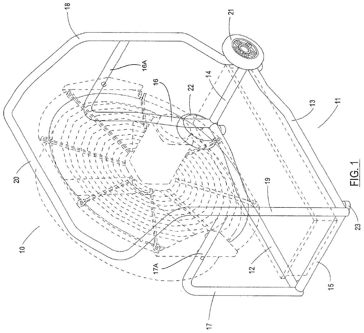
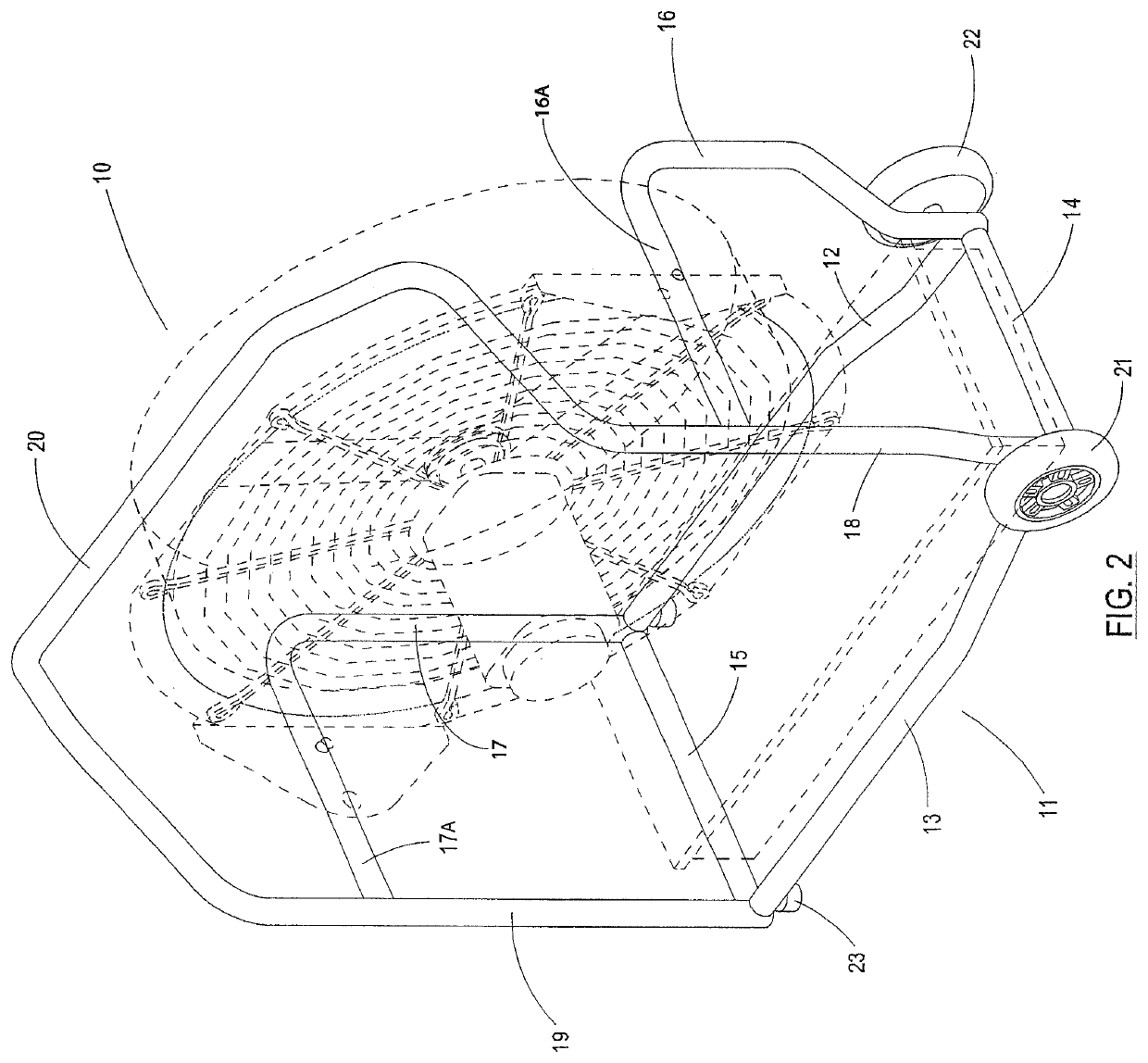
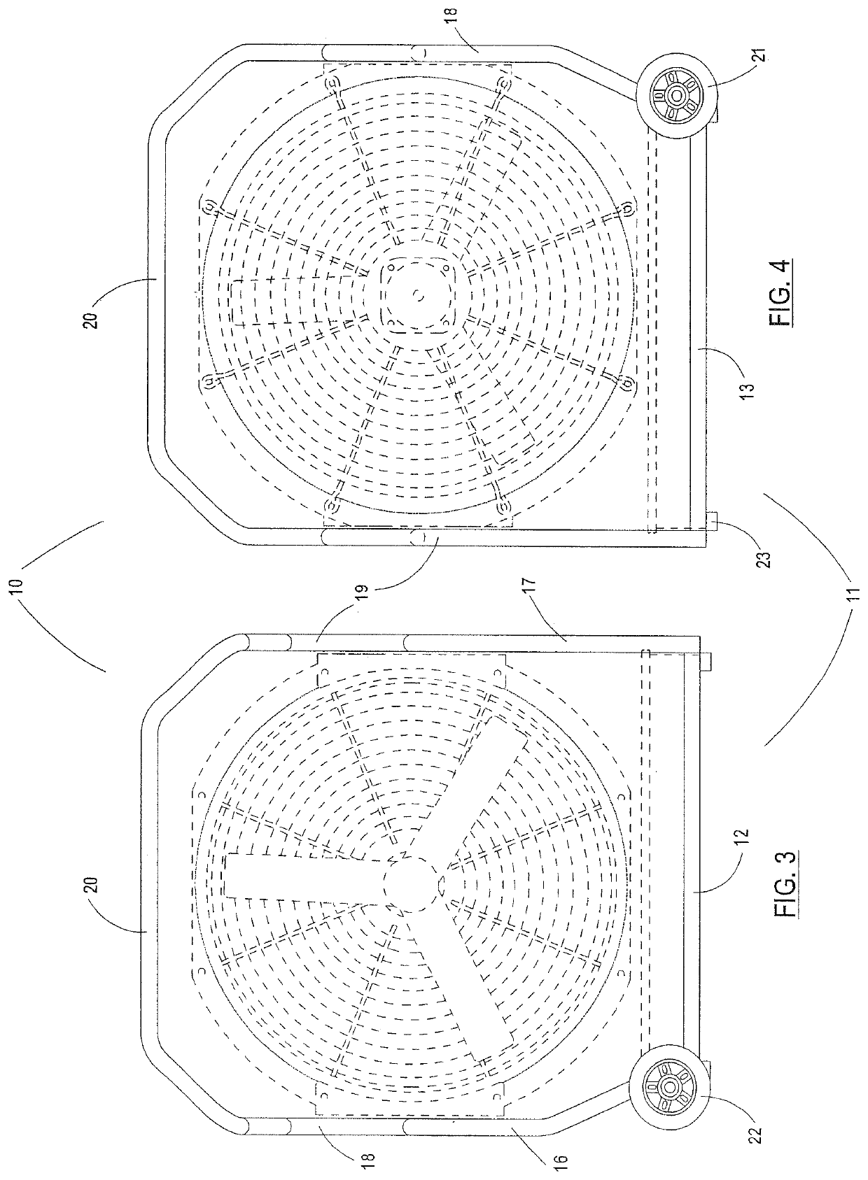
[0043]Referring to the drawings wherein like reference characters designate like or corresponding parts throughout the several views, and referring particularly to FIGS. 1-2, it is seen that this illustrated embodiment of the invention includes a support frame 10 made up of elongated sturdy members, preferably made of metal (such as, without limitation, aluminum, steel or the like), although embodiments may be made of other rigid and sturdy materials such as, without limitation, plastic or acrylic. It is important that the material from which members of the frame are made may be attached or adhered to each other, and that they allow mounting features to be provided for supporting a positive pressure blower. Solid or tubular materials may be used, or other strong structures such as I-beams.

[0044]The exemplary frame of the present invention shown in FIGS. 1-9 of the illustrations has a lower generally rectangular base 11 made up of a front member 12, rear member 13, side member 14 and...


PUM


Abstract

The present invention provides support frames for positive pressure blowers having one or more wheels mounted at a lower corner of the frame, wherein the wheels are mounted to roll in a direction that is perpendicular to the flow of air through the blower. This sideways orientation of the wheels allows a frame carrying a blower to be easily moved from side to side, such as when placed into or removed from a side compartment on an emergency vehicle, and allows such a frame carrying a blower to be easily tilted, turned and rolled around at the scene of a fire in much the same manner as a wheelbarrow. Embodiments of the invention may include an upper handle or grip which allows a user to control the frames by tilting and rolling them around on the wheels. Embodiments of the invention may include a support bracket for holding a battery or other power supply.

Description

PRIORITY CLAIM[0001]This application is a non-provisional of and claims the benefit of U.S. Provisional Application No. 62 / 455,173 filed on Feb. 6, 2017, and is also a non-provisional of and claims the benefit of U.S. Provisional Application No. 62 / 563,583 filed on Sep. 26, 2017, both of which provisional applications are incorporated herein by this reference in their entireties.BACKGROUND OF THE INVENTION1. Field of the Invention[0002]The present invention relates to firefighting equipment, and in particular to new and improved support frames for a positive pressure blower devices and related methods of use.2. Description of the Prior Art[0003]Modern techniques of fighting structural fires often involve the use of a positive pressure blower (fan) in order to remove smoke and provide ventilation inside burning buildings. The quick evacuation of smoke from a building decreases the potential for smoke damage, and improves visibility and breathing for fire fighters so that they may mor...

Claims


Application Information

Patent Timeline
Patent Type & Authority Patents(United States)
IPC IPC(8): F16M3/00F04D29/60F16M1/04F04D29/40F04D19/00
CPCF16M1/04F04D29/601F04D29/403F16M3/00F04D19/002
Inventor COFFMAN, III, LEROY B.ALLEN, WILLIAM T.
Owner TEMPEST TECH
Learn More