
Grow light assembly with secondary light modules angularly movable relative to primary light modules

a light assembly and light technology, applied in the direction of lighting and heating equipment, semiconductor devices for light sources, lighting support devices, etc., can solve the problems of only being able to project light from the top-down toward the plant, limiting the amount of light that is exposed to the lower portion of the plant, generating or producing extremely high or excessive heat, etc., to achieve the effect of optimizing the growth of plants

Active Publication Date: 2020-11-24
GROWGENICS LLC
View PDF29 Cites 26 Cited by
  • Summary
  • Abstract
  • Description
  • Claims
  • Application Information

AI Technical Summary

Benefits of technology

The patent is about a system that uses sensors to gather data about the environment and the position of plants to optimize their growth. This data can be used to control the frequency of light that the plants receive, which can affect how they grow and react to light. By analyzing this data and controlling the lighting, the system can provide consistent and repeatable growing conditions. The data can also be sold to other growers who may want to repeat the same product.

Problems solved by technology

One problem with such a configuration is that light can only be projected from the top-down toward the plant.
This limits the amount of light that is exposed to the lower portions of the plant such that most of the leaves below the top of the plant canopy are shaded and do not get the light need to stimulate effective growth.
In addition, the lights, bulbs or lamps often used, such as fluorescent or HPS bulbs, generate or produce extremely high or an excessive amount of heat.
By spacing the light from the plant such a great distance, the plant is not exposed to an efficient amount of photonic grow energy and will not produce or grow in the most efficient manner.
Other potential problems in the current industry of grow lights is the lack of consistency, the lack of ability to control the light output, as well as a lack of automation and repeatability.

Method used


Image

  • Grow light assembly with secondary light modules angularly movable relative to primary light modules
  • Grow light assembly with secondary light modules angularly movable relative to primary light modules
  • Grow light assembly with secondary light modules angularly movable relative to primary light modules

Examples


Embodiment Construction

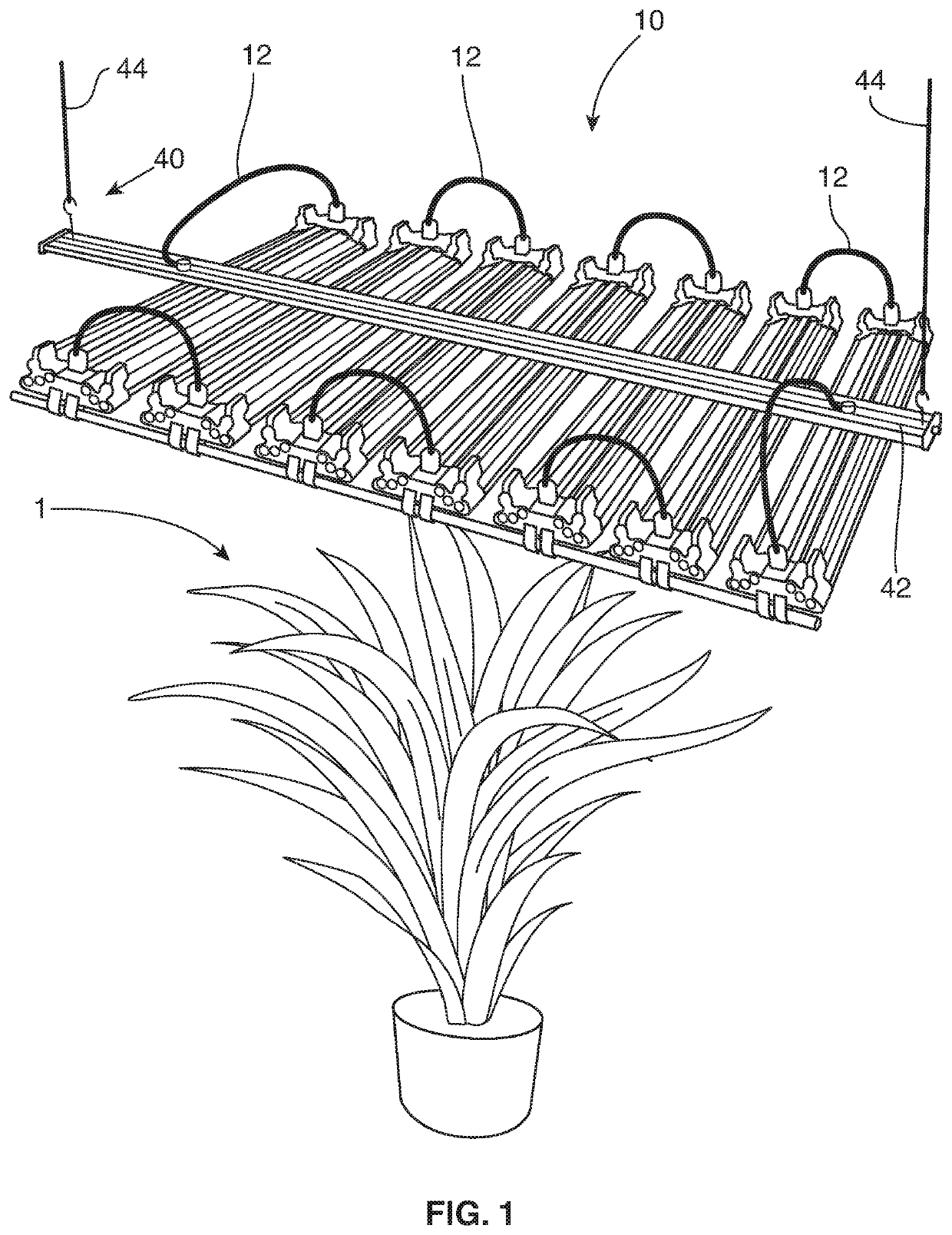
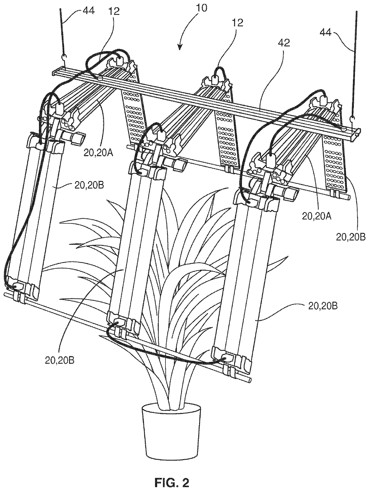
[0025]As shown in the accompanying drawings, and with particular reference to FIGS. 1 and 2, for example, the present invention is directed to a grow light assembly, generally shown as 10. As provided herein, the grow light assembly 10 of the various embodiments is structured and configured to facilitate the growth of one or more plants 1 by emitting light, e.g., by providing photosynthetic active radiation, upon the plant(s) 1 from one or more angles or positions.

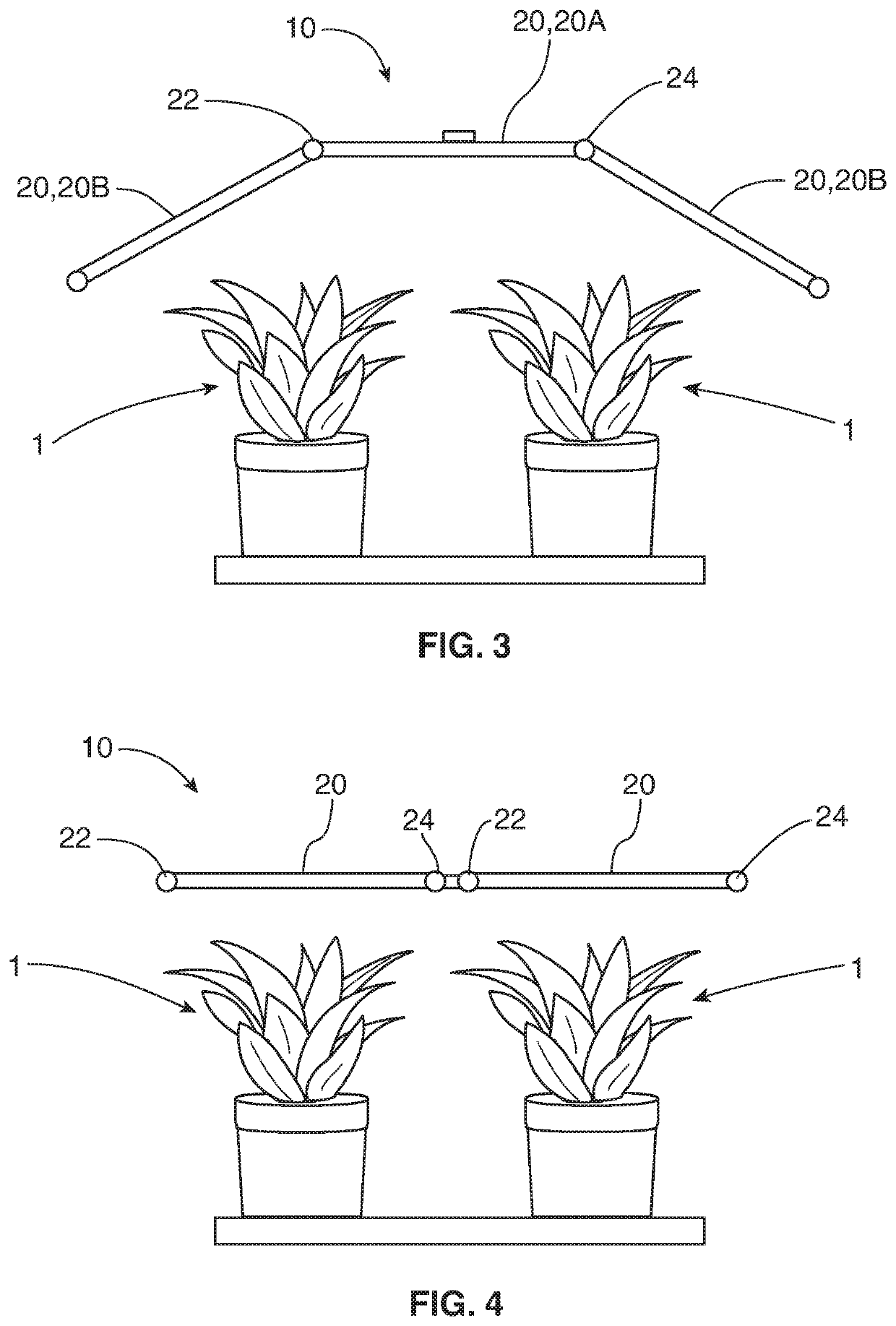
[0026]For instance, the grow light assembly 10 of at least one embodiment of the present invention comprises one or more light modules 20 that are spaced a distance from the plant(s) 1 or the plant canopy and which are adapted to shine or emit artificial light upon the plant 1 for stimulation of plant growth. In some embodiments, the grow light assembly 10 employs shape lighting technology that allows the one or more light modules 20 to be positioned or adjusted, for example, during the life cycle of the plant(s) 1, in ord...


PUM


Abstract

A grow light for stimulating plant growth is presented herein. The grow light includes a plurality of primary light modules with LEDs fixedly mounted to a support assembly and spaced a distance away from a plant canopy, and one or more secondary light modules movably or pivotally mounted to an end of one or more of the primary light modules. A positioning assembly is disposed interconnected light modules for manually or automatically movably disposing the secondary light modules into different angular positions relative to the plant. A height adjustment assembly is also include to movably position the light assembly, such as the plurality of primary light modules or the secondary light modules in a vertical direction. Additional features can be included, such as positioning sensors, environmental sensors, CO2 delivery systems, water cooling systems, ground wire interconnections, and light frequency control.

Description

FIELD OF THE INVENTION[0001]The present invention is generally directed to a light assembly or grow light structured to facilitate or stimulate the growth of plants, for example, in the field of horticulture, indoor gardening, hydroponics, aquaponics, indoor vertical grow farms, etc. In certain embodiments, the grow light includes one or more light modules that can be moved or adjusted, e.g., in a vertical, angular or horizontal direction, either manually or automatically, in order to maximize the stimulation of plant growth.BACKGROUND OF THE INVENTION[0002]Grow lights are often used to facilitate the growth of plants in many various indoor farm environments or indoor growing facilities. Conventionally, these grow lights incorporate or use fluorescent bulbs or high pressure sodium lamps (HPS) that are suspended or otherwise disposed directly above the plants in a straight downward facing direction. One problem with such a configuration is that light can only be projected from the to...

Claims


Application Information

Patent Timeline
IPC IPC(8): A01G7/04F21V21/15F21V29/56F21V23/00F21Y103/10F21Y115/10
CPCF21V23/003F21V29/56A01G7/045F21V21/15F21Y2103/10F21Y2115/10A01G9/249F21S2/005F21V21/26F21Y2105/16F21V23/0471
Inventor GENGA, JR., RICHARD A.PISHDADIAN, HAMID
Owner GROWGENICS LLC
Learn More