Control systems and throttle assemblies for vehicles having handlebars

a technology of control system and throttle assembly, which is applied in the direction of cycle control system, vehicle, cycle equipment, etc., can solve the problems of unfavorable “twist” throttle assembly, unfavorable rider engagement with the throttle, and difficulty in maintaining the grip of the rider, so as to reduce the cost and complexity, improve the effect of functionality and usability

Active Publication Date: 2020-11-24
KA GRP AG
View PDF13 Cites 6 Cited by
  • Summary
  • Abstract
  • Description
  • Claims
  • Application Information

AI Technical Summary

Benefits of technology

[0011]In this way, the control system and throttle assembly of the present invention afford improved functionality and usability in connection with handlebar-equipped vehicles while, at the same time, reducing the cost and complexity of manufacturing and assembling throttle assemblies which can operate reliably and predictably in a number of different operating conditions.

Problems solved by technology

However, depending on the type of vehicle, how the vehicle is used, and the preferences of the rider or rider, “twist” style throttle assemblies may be undesirable.
By way of non-limiting example, because the rider is holding onto a rotatable grip, excessive vehicle movement may result in undesired vehicle acceleration or deceleration caused by grip rotation as the rider's body moves relative to the vehicle.
By way of non-limiting example, if the rider moves from sitting to standing while on a vehicle with a “twist” throttle assembly, the transition to standing has a tendency to rotate the grip and cause deceleration.
Thus, the rider generally has to compensate for this rotation by adjusting their hand position, which may be disadvantageous under certain operating conditions.
In some applications, such as those where “twist” throttle assemblies are undesirable, vehicles may employ finger-actuated or thumb-actuated throttle assemblies.
While the unintended deceleration effect described above in connection with “twist” throttle assemblies is less pronounced with “lever” style throttle assemblies, the rider's ability to maintain engagement with the grip is complicated by the need to actively move their thumb relative to their palm in order to reach and move the lever.
Conventional “lever” style throttle assemblies may employ levers that are difficult for certain riders (e.g., those with relatively small hands) to maintain engagement with because of how they are positioned relative to the grip throughout their range of motion.
The result of such a lever orientation and configuration is that the rider may be forced to loosen their grasp on the grip under certain vehicle operating conditions.
Here, the rider may have to loosen or otherwise reposition their grasp of the grip, extend their thumb at awkward angles, and / or articulate their wrist to uncomfortable positions.
However, these types of throttle assemblies tend to be bulky, expensive to manufacture, and may be impractical for use with certain types of vehicles where the rider frequently changes body position and / or orientation.
For example, certain types of conventional “ergonomic” levers may be designed to position the rider's thumb in a “pocket” or otherwise behind a structural feature that helps guide the thumb into engagement but can significantly limit the rider's ability to engage the lever “pocket” when in certain riding positions.
Thus, these types of conventional “ergonomic” levers may limit the rider's ability to transition between sitting and standing, and the rider may be forced to engage the lever in a different manner (e.g., against a surface outside of the “pocket”) in certain riding positions.
This may result in the rider having to compensate for the change in hand position by applying a substantially different amount of force to the lever in order to achieve the same amount of lever actuation.

Method used


Image

  • Control systems and throttle assemblies for vehicles having handlebars
  • Control systems and throttle assemblies for vehicles having handlebars
  • Control systems and throttle assemblies for vehicles having handlebars

Examples


Embodiment Construction

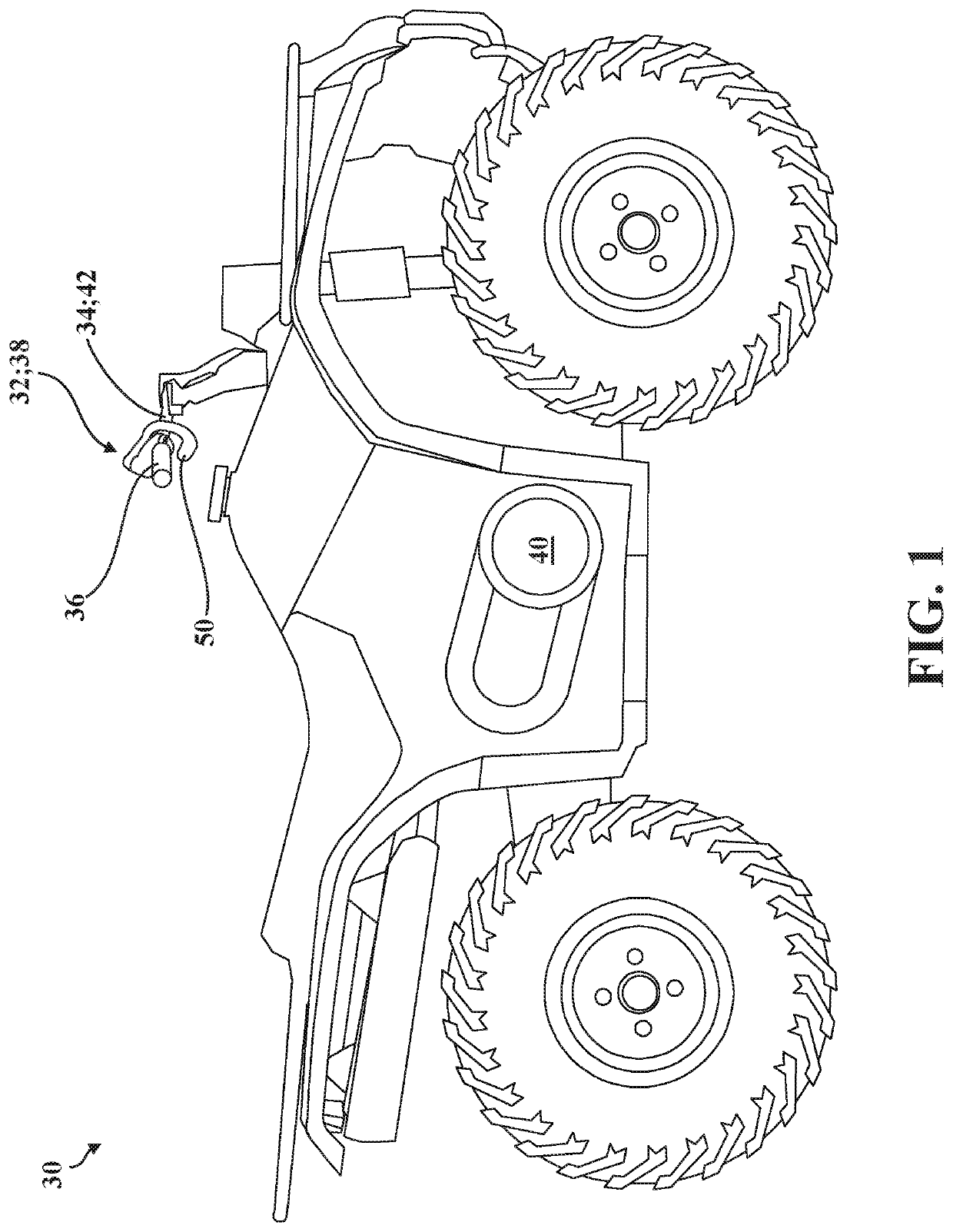
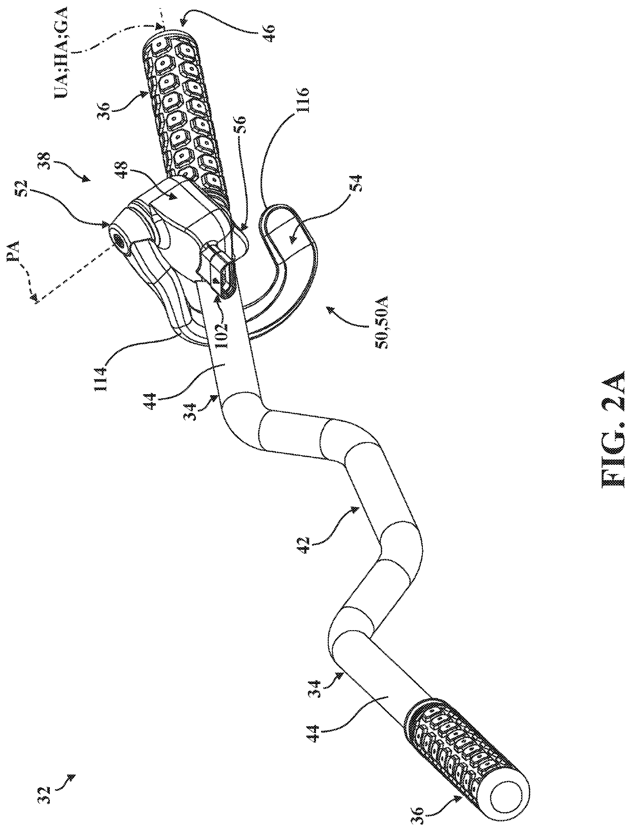
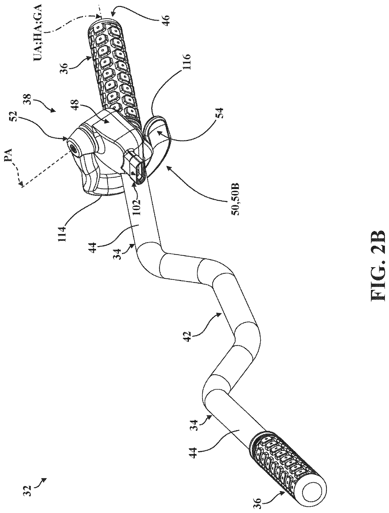
[0029]Referring now to the drawings, where like numerals indicate like or corresponding parts throughout the several views, a vehicle is generally shown at 30 in FIG. 1. The vehicle 30 comprises a control system 32 for use by rider (sometimes called an “operator” or a “driver”) of the vehicle 30. In the representative embodiment illustrated herein, the control system 32 includes one or more handlebars 34, grips 36, and a throttle assembly 38, each of which will be described in greater detail below.

[0030]The handlebars 34 are arranged for engagement by the rider to steer the vehicle 30 during use, and generally support the grips 36 which provide support to the rider's hands. The handlebars 34 also support the throttle assembly 38, which is adapted to enable the rider to control vehicle 30 acceleration and modulate speed, such as by regulating airflow into an internal combustion engine 40 which generates rotational torque used to propel the vehicle 30. However, those having ordinary s...


PUM


Abstract

A control system for use by a rider of a vehicle, comprising a handlebar with a grip extending along a grip axis, and a throttle assembly with a housing and mount adapted for attachment to the handlebar along a housing axis arranged coincident to the grip axis and laying in a longitudinal reference plane defining a forward side and a rider side. A thumb trigger is arranged for movement between a first trigger position and a second trigger position, and comprises a thumb pad arranged for engagement by the rider, and a trigger interface supported for rotation about a pivot axis defined by the housing and arranged at an oblique angle relative to the housing axis taken normal to the longitudinal reference plane such that at least a portion of the thumb pad remains on the rider side as the thumb trigger moves between the first and second trigger positions.

Description

CROSS-REFERENCE TO RELATED APPLICATION[0001]The subject patent application claims priority to and all the benefits of U.S. Provisional Patent Application No. 62 / 581,213 filed on Nov. 3, 2017, the disclosure of which is hereby incorporated by reference in its entirety.BACKGROUND OF THE INVENTION1. Field of the Invention[0002]The present invention relates, generally, to throttle assemblies for vehicles and, more specifically, to control systems and throttle assemblies for vehicles having handlebars.2. Description of the Related Art[0003]Conventional throttle assemblies known in the art are employed to allow a rider (also sometimes referred to as an “operator” or a “driver”) to selectively control operation of a vehicle. To this end, throttle assemblies are used to control vehicle acceleration and modulate vehicle speed, such as by regulating airflow into an internal combustion engine which generates rotational torque used to propel the vehicle. In certain types of vehicles, such as al...

Claims


Application Information

Patent Timeline
Patent Type & Authority Patents(United States)
IPC IPC(8): B62K23/06B62K11/14B62K5/01
CPCB62K23/06B62K11/14B62K5/01
Inventor HENGST, AARON
Owner KA GRP AG
Why Eureka
Try Eureka