
Turbomachine guide vanes with improved vane profile

a technology of guide vanes and turbomachines, which is applied in the direction of machines/engines, stators, liquid fuel engines, etc., can solve the problems of not being able to improve the distribution of air flow within the straightener stream, not being able to reduce losses, and not being able to achieve the improvement of loss improvement and size reduction required by new designs

Active Publication Date: 2020-11-24
SAFRAN AIRCRAFT ENGINES SAS
View PDF12 Cites 0 Cited by
  • Summary
  • Abstract
  • Description
  • Claims
  • Application Information

AI Technical Summary

Benefits of technology

The proposed geometry improves air flow distribution and reduces pressure losses by up to 2%, increasing efficiency and minimizing acoustic perturbations, while maintaining a hook-shaped leading edge configuration to limit noise.

Problems solved by technology

However, these geometries are not compatible with loss improvement and size reduction required by new designs.
However, the straightener proposed in this document does not make it possible to improve the distribution of air flow within the straightener stream, nor to reduce losses.

Method used


Image

  • Turbomachine guide vanes with improved vane profile
  • Turbomachine guide vanes with improved vane profile
  • Turbomachine guide vanes with improved vane profile

Examples


Embodiment Construction

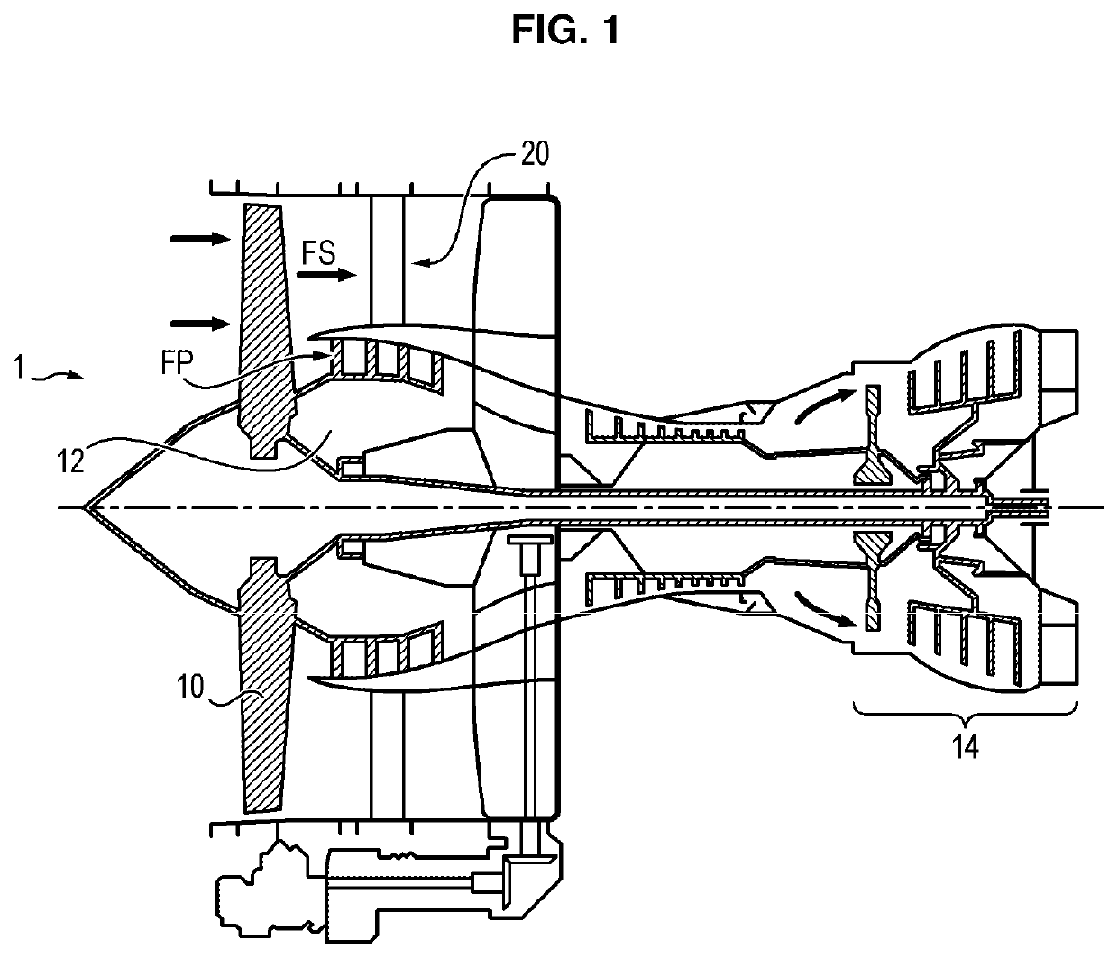
[0030]With reference to FIG. 1, a bypass turbomachine 1 has, as described previously, a fan 10 and a straightener 20 of the OGV type, to straighten a secondary air flow FS coming from the fan.

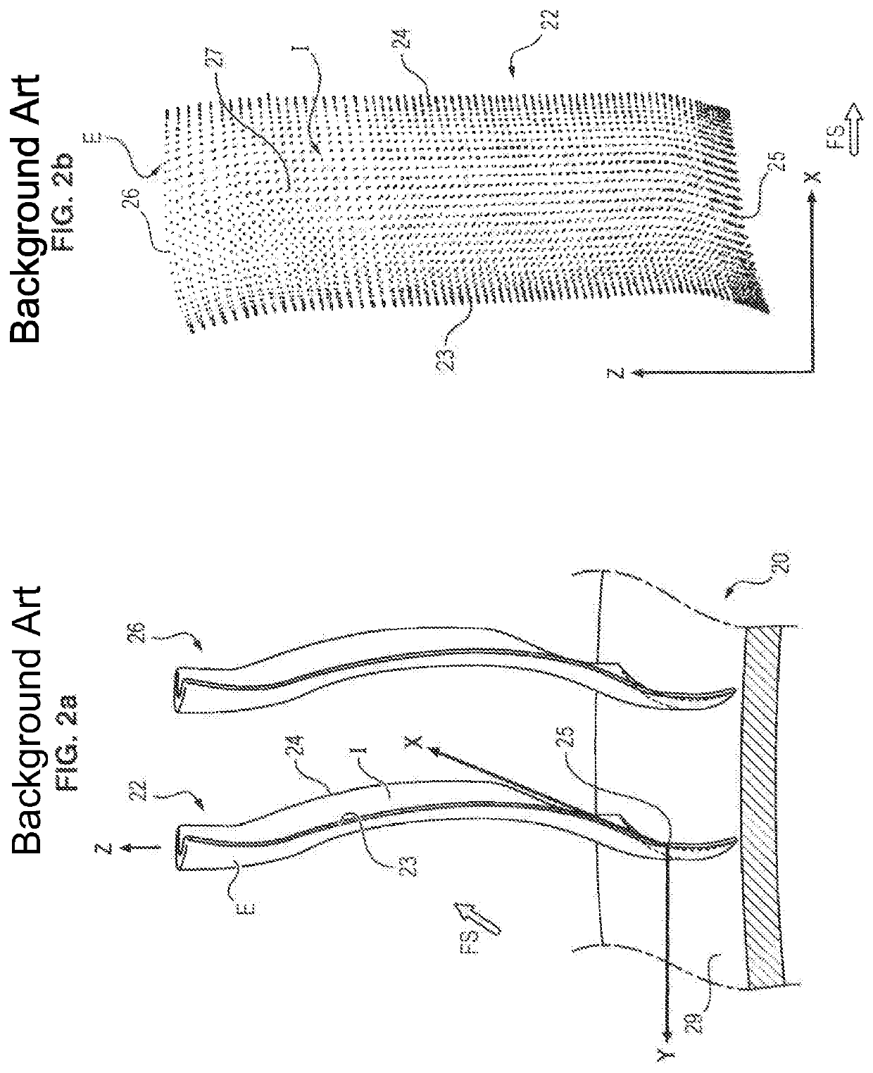
[0031]With reference to FIG. 2a, the straightener 20 includes a plurality of vanes 22 evenly distributed around a ring 29 centered on the axis of the turbomachine (not shown in the figure). The vanes shown in FIGS. 2a and 2b are not representative of the geometry adopted by the invention.

[0032]Each vane 22 includes a leading edge 23, and a trailing edge 24, extending between a radially inward end 25, called the root of the vane, and a radially outward end 26, called the tip of the vane. The leading edge 23 the trailing edge 24 delimit an intrados I and an extrados E.

[0033]The following notation is also used: X is the direction of the axis of the turbomachine or engine axis, Y is the tangential direction relative to the ring 29 of the straightener, and Z is the radial direction, along which each...


PUM


Abstract

A set of turbomachine guide vanes including plural vanes arranged around an annulus, each vane having a leading edge extending between root and tip ends, the leading edge offset between these two ends being greater than 10% of the blade height. A tangential stacking of the guide vanes towards the suction face side, the curve of tangential stacking, of the position, in the direction tangential to the annulus, of centers of gravity of successive vane cross sections along the vane height, is a curve that increases constantly towards the suction face side. The curve, near the vane tip end, has an accentuated gradient towards the suction face side compared with the rest of the curve, and has a mean gradient near the vane tip end that is greater than at least 1.2 times the mean gradient of the curve over the portion between 30% and 90% of the vane height.

Description

CROSS-REFERENCE OF RELATED APPLICATION[0001]The present application is a continuation of U.S. patent application Ser. No. 14 / 413,042, filed Jan. 6, 2015, which is a continuation of International Application No. PCT / FR2013 / 051531, Jun. 28, 2013, and claims priority to French Patent Application No. 12-56532, filed Jul. 6, 2012, the entire contents of which are incorporated herein by reference.FIELD OF THE INVENTION[0002]The invention relates to the field of turbomachine straighteners and to turbomachines including such straighteners.PRIOR ART[0003]A bypass turbomachine for aircraft propulsion is shown in FIG. 1. It includes a fan 10 delivering a stream of air of which a central portion, called the primary flow FP, is injected into a compressor 12 which supplies a turbine 14 which drives the fan.[0004]The peripheral portion, called the secondary flow FS, of the air stream is for its part ejected into the atmosphere to supply a portion of the thrust of the turbomachine 1, after having p...

Claims


Application Information

Patent Timeline
Patent Type & Authority Patents(United States)
IPC IPC(8): F01D9/04F01D5/14F01D1/04F04D29/54
CPCF01D1/04F04D29/544F01D9/04F01D5/141F01D9/041F05D2240/121F05D2220/36Y02T50/60F05B2250/71
Inventor COJANDE, PRADEEPREISS, HANNA
Owner SAFRAN AIRCRAFT ENGINES SAS
Features
  • Generate Ideas
  • Intellectual Property
  • Life Sciences
  • Materials
  • Tech Scout
  • Unparalleled Data Quality
  • Higher Quality Content
  • 60% Fewer Hallucinations
Learn More