
Evacuation of a film chamber

Active Publication Date: 2020-11-24
INFICON GMBH
View PDF32 Cites 1 Cited by
  • Summary
  • Abstract
  • Description
  • Claims
  • Application Information

AI Technical Summary

Benefits of technology

The invention describes a device that can quickly and efficiently evacuate a film chamber to a desired pressure. The device includes two vacuum pumps, a buffer chamber, and a throttle valve. When the second vacuum pump is connected to the film chamber, it evacuates the buffer chamber and reaches the end pressure of the film chamber. The buffer chamber is then used to further evacuate the film chamber, reducing the time needed to reach the desired pressure. The first vacuum pump has a higher suction capacity and end pressure than the film chamber, while the second vacuum pump has lower suction capacity and end pressure than the buffer chamber. This combination of vacuum pumps is lightweight, portable, and fast in evacuating the film chamber to the required pressure.

Problems solved by technology

Such pumps are heavy and require high electric power for operation.
Smaller, lighter pumps either have a high suction capacity or can reach a low pressure so that they are not suited as the single replacement of conventional pumps.

Method used


Image

  • Evacuation of a film chamber
  • Evacuation of a film chamber

Examples


Embodiment Construction

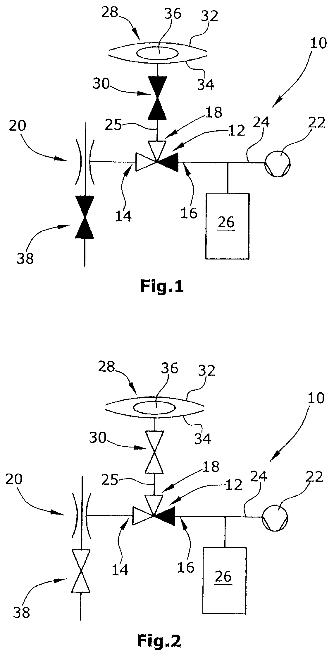
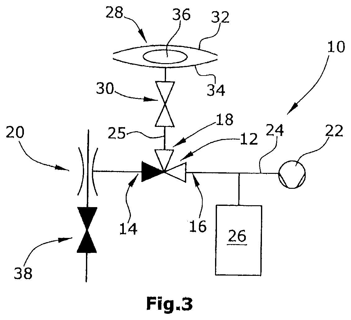
[0019]A central core element of a device according to the example embodiments is a 3 / 2-way valve 12 having three ports 14, 16, 18 and two operating paths. A first vacuum pump 20 in the form of a Venturi pump is connected with the first port 14. A second vacuum pump 22 in form of a displacement pump is connected with the second port 16. The pipeline 24 connecting the second port 16 with the second vacuum pump 22 is connected with a buffer chamber 26 in a gas-conveying manner. The third port 18 is connected with the film chamber 28 via a pipeline 25. A stop valve 30 is arranged in the pipeline 25 between the film chamber 28 and the third port 18. As an alternative, it is conceivable that each of the two vacuum pumps 20, 22 is connected with the film chamber 28 via an own separate pipeline.

[0020]The film chamber 28 includes or consists of two film layers 32, 34 between which the specimen 36 is arranged.

[0021]The Venturi pump 20 is connected with a valve 38 so as to be able to control t...


PUM


Abstract

A device for evacuating a film chamber using a pump system that comprises at least two vacuum pumps, designed to evacuate the film chamber alternately. A suction capacity of the first vacuum pump is greater than that of the second vacuum pump and the final pressure achievable by the first vacuum pump is less than that of the second vacuum pump.

Description

CROSS-REFERENCE TO RELATED APPLICATIONS[0001]This application is the United States national phase of International Application No. PCT / EP2014 / 069584 filed Sep. 15, 2014, and claims priority to German Application No. 10 2013 219 464.1 filed Sep. 26, 2013, the disclosures of which are hereby incorporated in their entirety by reference.BACKGROUND OF THE INVENTIONField of the Invention[0002]The invention relates to a device and a method for evacuating a film chamber.Description of Related Art[0003]Film chambers are made of a flexible, soft material—mostly films—and are used in detecting leaks in packages. A specimen to be examined for a leak is placed in the film chamber. Most often, the specimen is a food package also made of a flexible material. The film chamber surrounding the specimen is evacuated. Thereafter, the pressure or the gas in the film chamber is monitored so as to test the tightness of the specimen and to detect a possible leak in the specimen.[0004]Conventional film cham...

Claims


Application Information

Patent Timeline
IPC IPC(8): F04F5/54G01M3/20F04F5/22G01M3/22F04F5/44
CPCG01M3/205G01M3/229F04F5/44F04F5/54F04F5/22
Inventor DECKER, SILVIODAUENHAUER, MICHAELWETZIG, DANIELBRUHNS, HJALMAR
Owner INFICON GMBH
Learn More