
Mid-body marking projectile

a marking and projectile technology, applied in the field of mid-body marking projectiles, can solve the problems of ricochets, post-wall failure, powder ejection, etc., and achieve the effect of reducing the risk of fragment ricochets and mass reduction

Active Publication Date: 2020-11-24
COMPANHIA BRASILEIRA DE CARTUCHOS
View PDF42 Cites 5 Cited by
  • Summary
  • Abstract
  • Description
  • Claims
  • Application Information

AI Technical Summary

Benefits of technology

The patent describes a cartridge that can be used in a machine gun or cannon. The cartridge contains a marking projectile that can identify the location of an impact. The projectile breaks up on impact, reducing the risk of ricochet. This reduces the risk of injury and damage to the environment. The technical effect of this invention is to provide a safer and more efficient way to mark the location of a projectile's impact.

Problems solved by technology

At impact in the vicinity of a target, impact forces act on the projectile body inducing a wall failure that expels marking powder into the atmosphere.
Generally, a designer can use a typically polymer that will shatter and separate from the projectile at impact, where the nose undergoes an abrupt de-acceleration, and the inertia in the base squeezes the mid-body marker wall, causing failure and allowing forces to eject the marking powder, and allowing the heavier metal base to continue forward movement after wall failure, compressing and causing ejection of the powder, post wall failure.
Ranges with exposed rocky outcrops frequently produce ricochets.

Method used


Image

  • Mid-body marking projectile
  • Mid-body marking projectile
  • Mid-body marking projectile

Examples


Embodiment Construction

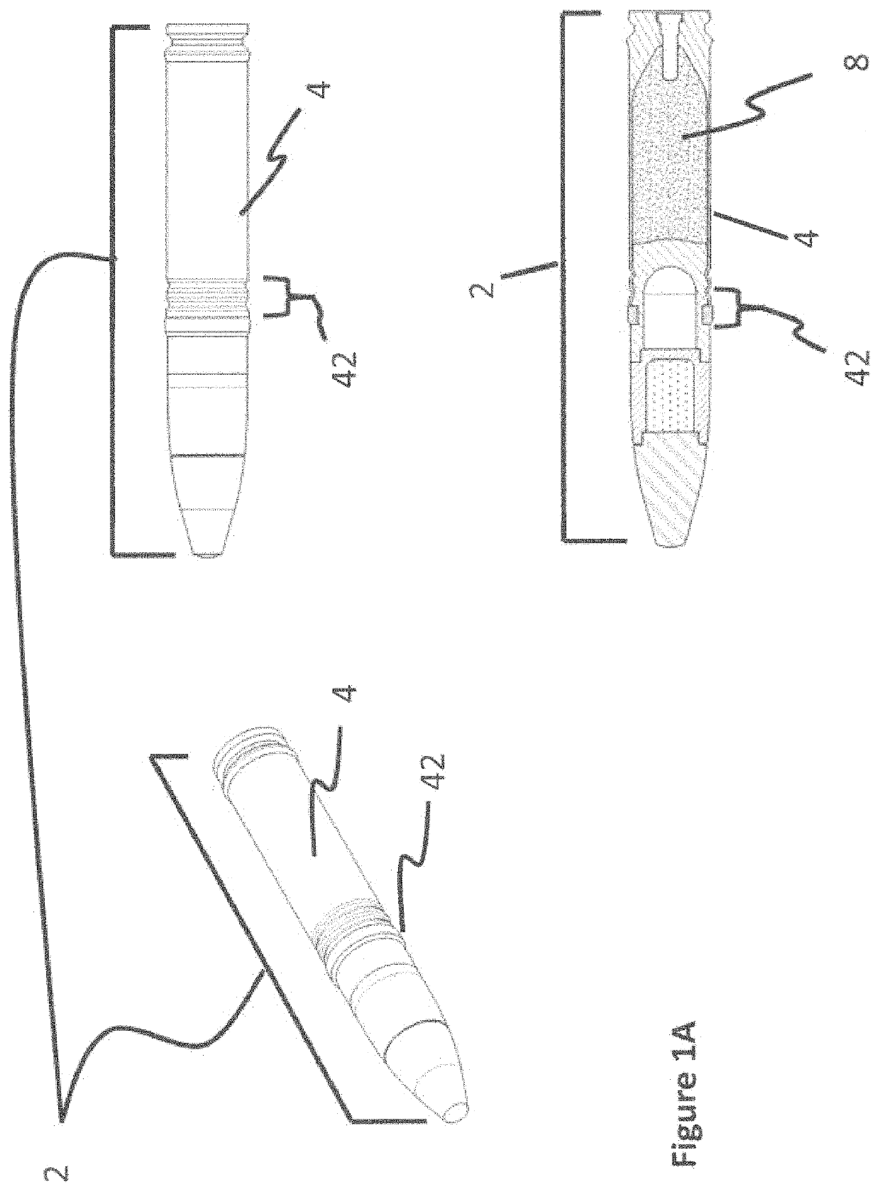
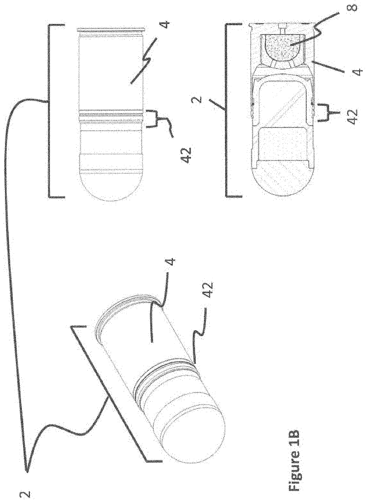
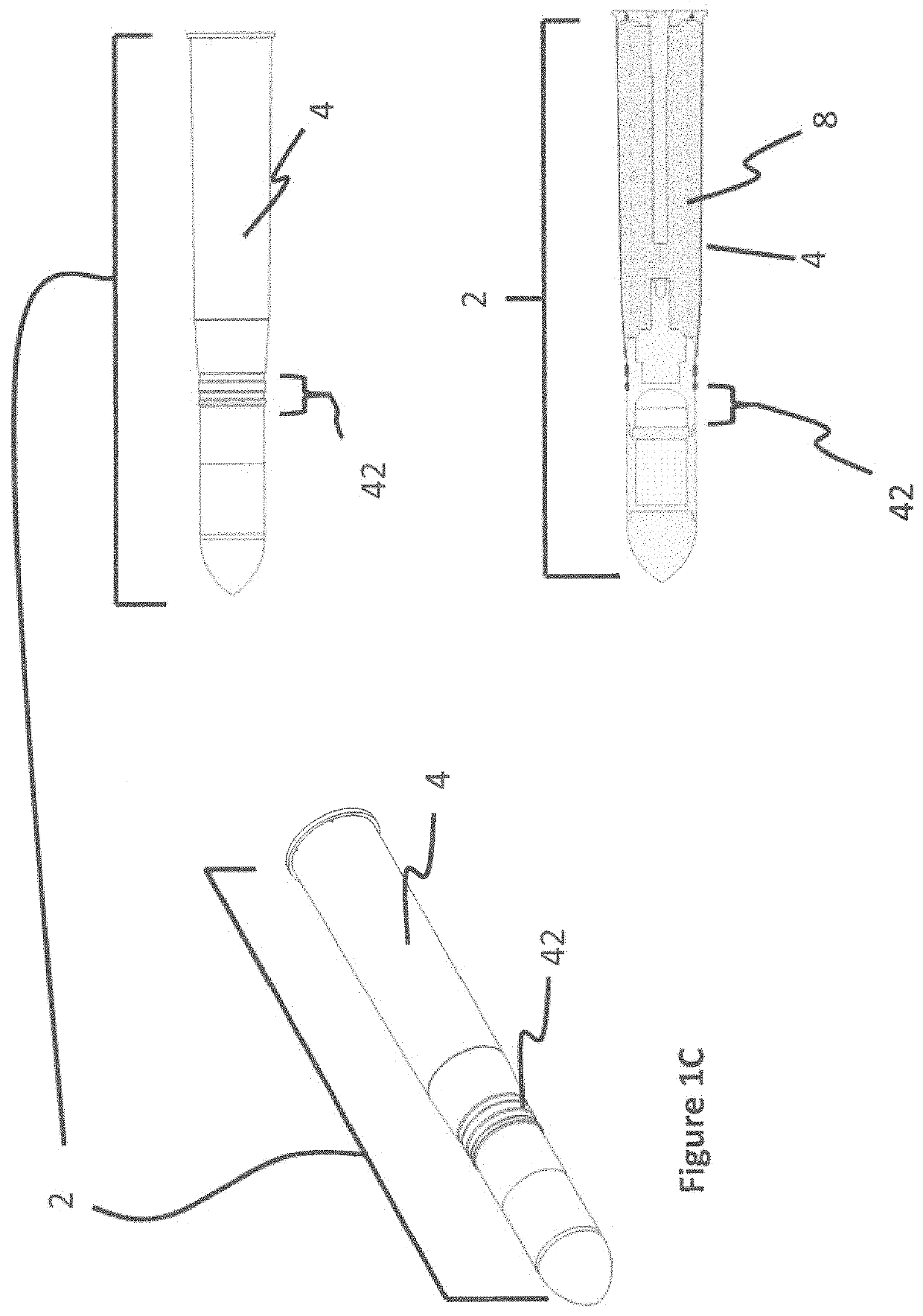
[0008]The preferred embodiments of the present invention will now be described with reference to FIGS. 1A to 11F of the reference drawings. Identical elements of the various figures are designated with the same reference numbers, incorporated into three different types of gun fired cartridges depicted herein in three configurations—30 mm×113 cartridge, 40 mm×53 cartridge and a 105 mm Tank cartridge.

[0009]FIGS. 1A-8C depicts embodiments of the cartridge configuration in 30 mm, 40 mm and 105 mm projectiles.

[0010]FIG. 1A depicts 30 mm gun fired cartridges (2) with driving bands (42). A cartridge case (4) encloses propellant powder (8).

[0011]FIG. 1B depicts 40 mm gun fired cartridges (2) with driving bands (42). A cartridge case (4) encloses propellant powder (8).

[0012]FIG. 1C depicts 105 mm (tank) gun cartridges (2) with driving bands (42). A cartridge case (4) encloses propellant powder (8).

[0013]FIG. 2A depict a 30 mm cartridge (2) configured in a belt of ammunition (6).

[0014]FIG. 2B...


PUM


Abstract

A cartridge incorporating a projectile assembly, the projectile assembly having a base, mid body component housing a marking powder and lighter metallic nose cap. The projectile's mid-body component undergoes wall failure at impact, the wall failure is induced as forward momentum of the base and other residual forces act to expel the marking powder from the projectile, the manner of ejection suspending a low density material with contrast dye, in the vicinity of the impact, providing a gunner with visual cue in regard to a projectile's impact location.

Description

CROSS REFERENCE TO RELATED APPLICATION[0001]This present application claims benefit of priority from U.S. Provisional Application Ser. No. 62 / 549,596 filed 24 Aug. 2017, entitled “Mid-Body Marking Projectile.”BACKGROUND OF THE INVENTION[0002]Many militaries around the world typically become increasingly sensitive to the environmental impact of military training. Unexploded ordnance and associated clean up liabilities, are a significant consideration for procurement officials purchasing ammunition. In the field of spin stabilized, gun fired ordnance the US Army Research Development and Engineering Center (ARDEC) located at Picatinny Arsenal, developed the inexpensive M781 “chalk” round, that provided a visual signature for draft era conscripted soldiers. The frangible ogive of the M781 projectile was fabricated from plastic material, the plastic ogive further containing a marking powder. Normally, a training cartridge would have to survive a standard five-foot drop test; however, in ...

Claims


Application Information

Patent Timeline
Patent Type & Authority Patents(United States)
IPC IPC(8): F42B12/40F42B12/50F42B8/16
CPCF42B12/40F42B8/16F42B12/50F42B8/14
Inventor MORENO, MARCELOBRUNO, NICOLAS HORACIO
Owner COMPANHIA BRASILEIRA DE CARTUCHOS
Learn More