Imaging radar sensor with horizontal digital beam forming and vertical object measurement by phase comparison in mutually offset transmitters

a technology of mutual offset transmitters and radar sensors, which is applied in the direction of individually energised antenna arrays, instruments, and reradiation, can solve the problems of distortion of the amplitude characteristic of the antenna diagram, and achieve the effect of mechanical beam sweep and calibration avoidan

Active Publication Date: 2020-12-22
CRUISE MUNICH GMBH
View PDF69 Cites 7 Cited by
  • Summary
  • Abstract
  • Description
  • Claims
  • Application Information

AI Technical Summary

Benefits of technology

[0009]The object of the invention is to make available a device, a method and a radar system with which the disadvantages described above such as mechanical beam sweep and calibration are avoided. Furthermore, it is the object of the invention to make available a device and a method with which a vertical position of an object can be determined.

Problems solved by technology

However, a disadvantage of this method in practice is that by means of structures upstream of the sensor, such as radomes, plastic bumpers and similar coverings, the amplitude characteristic of the antenna diagrams is distorted.

Method used


Image

  • Imaging radar sensor with horizontal digital beam forming and vertical object measurement by phase comparison in mutually offset transmitters
  • Imaging radar sensor with horizontal digital beam forming and vertical object measurement by phase comparison in mutually offset transmitters
  • Imaging radar sensor with horizontal digital beam forming and vertical object measurement by phase comparison in mutually offset transmitters

Examples


Embodiment Construction

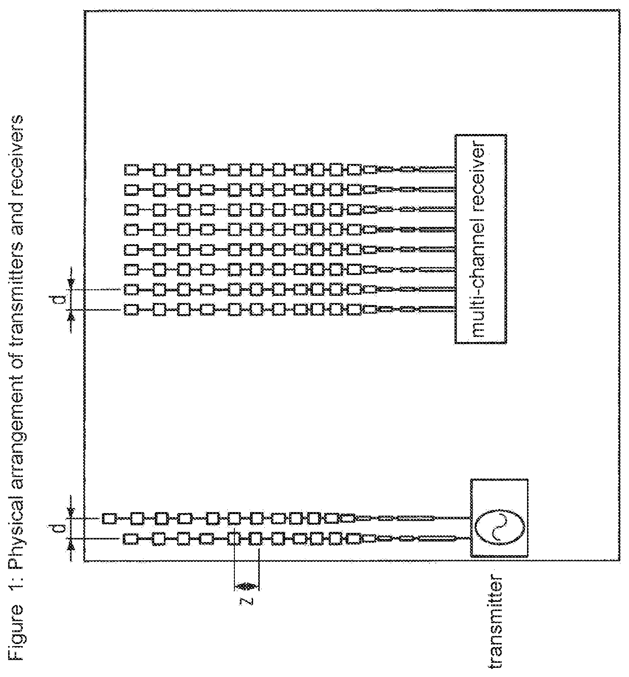
[0015]The sensor consists at least of two transmitting antennas and an array of receiving antennas within the distance d. The phase centres of the transmitting antennas are offset in the vertical by the distance z which is smaller than or equal to half the free space wavelength (1) of the emitted signal, in particular in order to guarantee clarity and in order to avoid any ambiguity. The switchable transmitting antennas therefore have different vertical positions of the phase centres, i.e. a first position of the phase centre of the first switchable transmitting antenna, a second position of the phase centres of the second switchable transmitting antenna, etc., by means of which the vertical positions of the phase centres are different, which phase centres are offset vertically by the distance z. In the horizontal the second antenna is offset to the first antenna by the line spacing of the receiving array d.

[0016]For the line spacing of the receiving array d the following applies:

[0...


PUM


Abstract

According to the invention, a device and a method are provided for determining the position of an object, in particular a moving object, in the three-dimensional space. The device comprises at least two switchable transmitting antennas having a different vertical position of the phase center as well as a plurality of receiving antennas which are arranged in series. The transmitting antennas are arranged in the horizontal direction and at a distance that corresponds to the distance of the receiving antennas. The transmitting antennas are vertically offset with respect to each other by a value that is less than or equal to half the free-space wavelength of the transmitted signal. The transmitting antennas can otherwise be arranged at any position around the receiving antenna. Horizontal beam sweep across a wide angular range is carried out according to the method of “digital beamforming”. The measurement of the vertical object position is carried out by phase measurement between the antenna beams when the transmitting antennas are sequentially switched.

Description

TECHNICAL FIELD OF APPLICATION[0001]The invention relates to a method for measuring the vertical position of objects with a radar sensor which carries out two interleaved horizontal scans.[0002]Millimeter wave radar sensors, e.g. for automotive and aeronautical applications, should exhibit a compact and inexpensive construction.[0003]The detection is restricted to just one plane (mostly the horizontal plane), as is the case with most automotive radar sensors, and so this can take place inexpensively by using planar antennas and a number of receivers. The beamforming and control takes place here according to the principle of “digital beamforming”.[0004]As the demand for reliability increases, in particular radar sensors in the automotive domain should be capable of distinguishing between irrelevant obstacles such as bridges and sign gantries and objects lying on the road which pose a risk to the road traffic.[0005]In the aeronautical domain these sensors have also been used in recent...

Claims


Application Information

Patent Timeline
Patent Type & Authority Patents(United States)
IPC IPC(8): G01S13/931G01S13/34G01S13/42G01S13/935H01Q25/02G01S13/44G01S13/536H01Q21/06H01Q3/26H01Q1/32H01Q13/20G01S7/41H01Q3/24
CPCG01S13/424H01Q3/24G01S13/345G01S13/536G01S7/41H01Q3/26G01S13/4445H01Q13/206G01S13/931G01S13/4454H01Q21/065H01Q25/02H01Q1/32G01S13/935
Inventor TRUMMER, GUENTHER
Owner CRUISE MUNICH GMBH
Why Eureka
Try Eureka