
Dock assembly and method of construction thereof

Active Publication Date: 2020-12-29
CRESCENT EQUIP CO
View PDF13 Cites 0 Cited by
  • Summary
  • Abstract
  • Description
  • Claims
  • Application Information

AI Technical Summary

Benefits of technology

The present invention provides a dock assembly and a method of constructing it. The dock assembly includes first and second dock sidewalls joined via a first vertical receiver tube, and second and fourth dock sidewalls joined via a second vertical receiver tube. The first and third dock sidewalls are positioned side by side and securely joined using connector keys and lock bolts. The dock assembly is designed to provide a safe and secure connection between the dock sidewalls and the vertical receiver tubes. The technical effects of the invention include increased stability and durability of the dock assembly, as well as improved operational efficiency and reliability.

Problems solved by technology

Docks of wood construction allow for easy removal and / or replacement of deck boards, whereas aluminum docks with aluminum deck planks welded into the sidewall do not easily accommodate deck disassembly.
The small clearance of a typical dock freeboard elevation makes connection difficult or impossible for one person.
This difficulty can foster complacency and a disregard for best practices.
The installer might not connect hardware properly or might omit some parts entirely.
In rough water conditions, the frame sidewalls can undergo extreme cyclic loads.
The result can be brinelling of the aluminum at an attachment site, if metal hardware is used to connect metal (e.g., aluminum) docks in a conventional manner.
Moreover, if the sidewall is deformed underneath the fastener, further degradation will be inevitable, resulting in loss of the connection clamp load.
Floating concrete docks are prone to connection failure due to the compressibility of the wooden whaler used to sandwich the concrete floatation cells together.
Often, however, a scheduled maintenance plan is ignored, turning maintenance into repair, though usually only after a connection-related failure has occurred.

Method used


Image

  • Dock assembly and method of construction thereof
  • Dock assembly and method of construction thereof
  • Dock assembly and method of construction thereof

Examples


Embodiment Construction

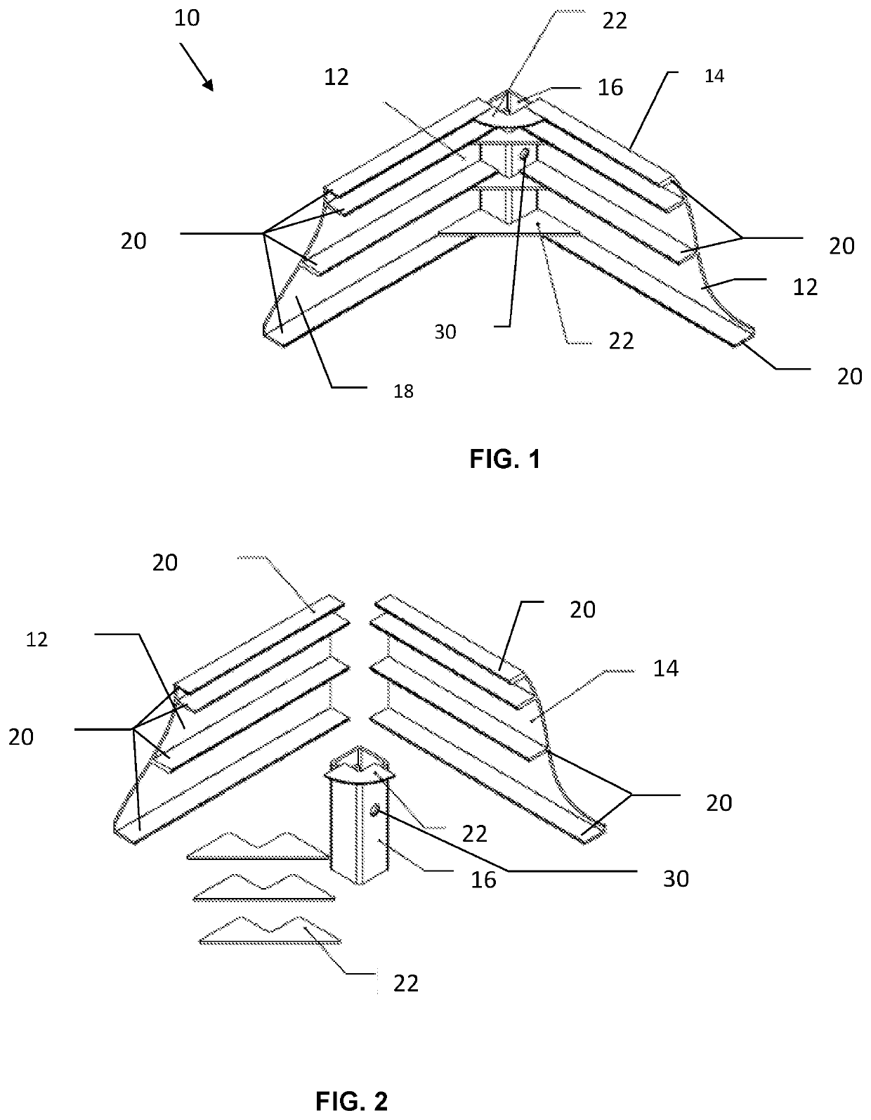
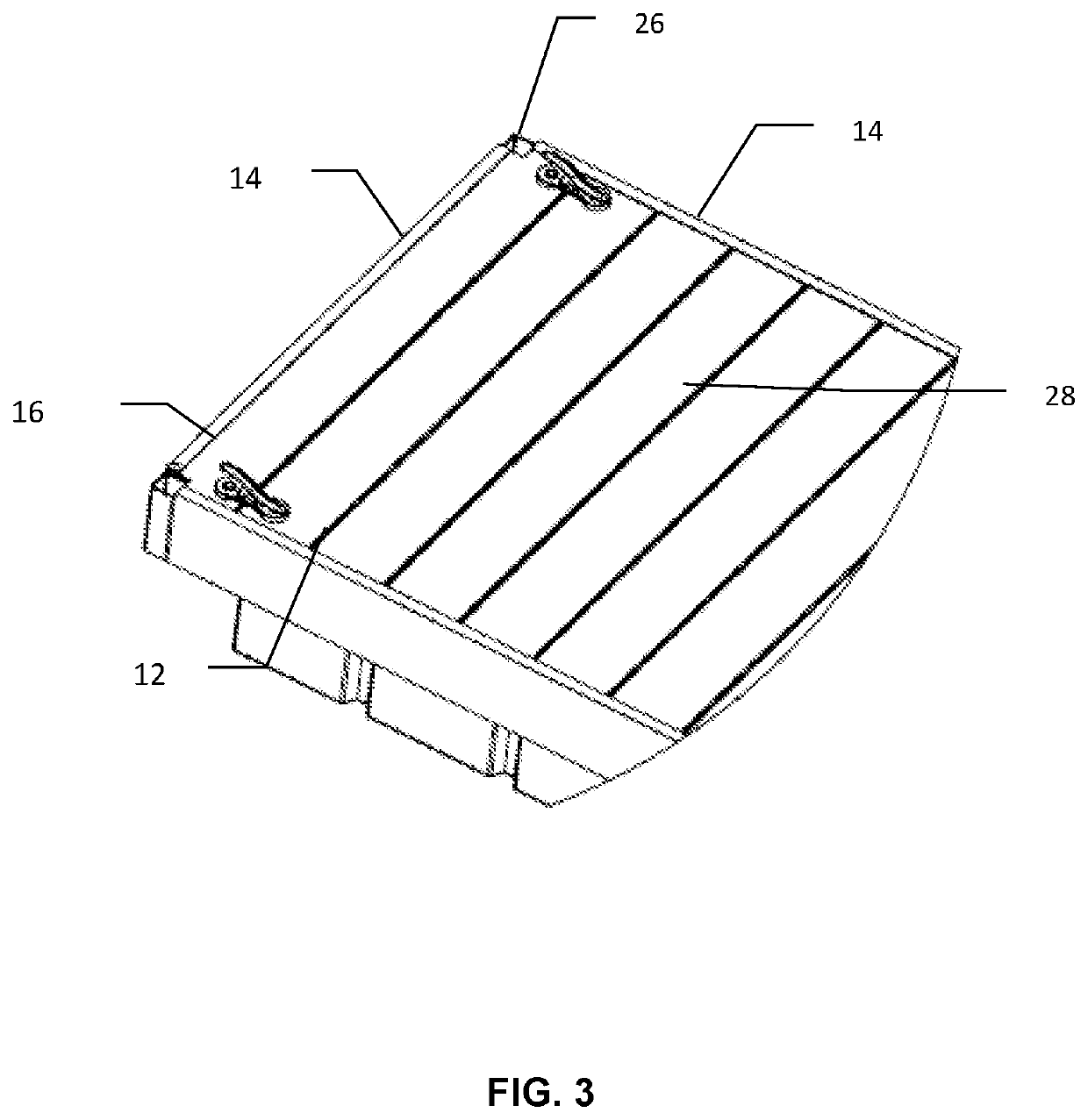
[0026]Referring to FIGS. 1-2, a dock assembly 10 includes a first dock sidewall 12 and a second dock sidewall 14 joined at 90 degrees via a first vertical receiver tube 16 positioned between adjacent ends of the first dock sidewall 12 and the second dock sidewall 14. The first and second dock sidewalls 12 and 14 each includes a peripheral surface 18 and a plurality of horizontal surfaces 20 extending from the peripheral surface 18. The first and second dock sidewall 12 and 14 are fixed to the first vertical receiver tube 16 via a first set of gusset plates 22 fastened to the plurality of horizontal surfaces 20 of the first dock sidewall 12 and the second dock sidewall 14, respectively.

[0027]The first set of gusset plates 22 includes a top gusset plate configured to be positioned at an upper periphery of the first receiver tube 16 and attached to an upper horizontal surface 20. The rest of the first set of gusset plates 22 are attached to the lower horizontal surfaces 20 of the first...


PUM


Abstract

A dock assembly includes a first and a second dock sidewall joined via a first vertical receiver tube positioned between adjacent ends of the first dock sidewall and the second dock sidewall. A third dock sidewall is joined with the second dock sidewall via a second vertical receiver tube positioned between adjacent ends of the second dock sidewall and the third dock sidewall. A fourth and a fifth dock sidewalls are joined via a third vertical receiver tube positioned between adjacent ends of the fourth dock sidewall and the fifth dock sidewall. The second and the fifth dock sidewalls are positioned side by side such that respective sides of the first and third receiver tubes are abutting each other. The first and third receiver tubes are securely joined by inserting respective upper and lower connector keys dimensioned to fit into respective sockets of the first and third receiver tubes.

Description

CROSS-REFERENCE TO RELATED APPLICATION[0001]This application claims the benefit of U.S. Provisional Patent Application Ser. No. 62 / 590,719, filed on Nov. 27, 2017, the contents of which applications are herein incorporated by reference in their entirety.FIELD OF THE INVENTION[0002]The present invention relates to a dock assembly, and more particularly, to a floating dock assembly and method of construction thereof.BACKGROUND OF THE INVENTION[0003]A common way of connecting floating dock assemblies is to install connection hardware from below and underneath the dock sections to be connected. Another way of connecting floating dock assemblies involves partial disassembly of deck components to allow access to fastener locations at the ends of the dock. Docks of wood construction allow for easy removal and / or replacement of deck boards, whereas aluminum docks with aluminum deck planks welded into the sidewall do not easily accommodate deck disassembly.[0004]A common approach to connecti...

Claims


Application Information

Patent Timeline
IPC IPC(8): B63C1/02
CPCB63C1/02B63B35/38
Inventor WAY, ROBERT
Owner CRESCENT EQUIP CO
Learn More