Motor control apparatus and method of controlling the same

a motor control and motor technology, applied in the direction of dynamo-electric converter control, dynamo-electric gear control, dynamo-electric brake control, etc., to achieve the effect of high accuracy and shortening the activation tim

Active Publication Date: 2021-01-12
CANON KK
View PDF7 Cites 0 Cited by
  • Summary
  • Abstract
  • Description
  • Claims
  • Application Information

AI Technical Summary

Benefits of technology

[0006]The present invention provides a technique for shortening activation time while realizing high accuracy motor control.

Problems solved by technology

However, in a case of shortening an amount of time from activation until the motor reaches a target rotation speed, it is necessary to drive by a high torque to increase the acceleration of the motor.

Method used


Image

  • Motor control apparatus and method of controlling the same
  • Motor control apparatus and method of controlling the same
  • Motor control apparatus and method of controlling the same

Examples


first embodiment

[0019]Description is given below by taking, as an example, an electrophotographic method image forming apparatus as a first embodiment of a motor control apparatus according to the present invention.

[0020]

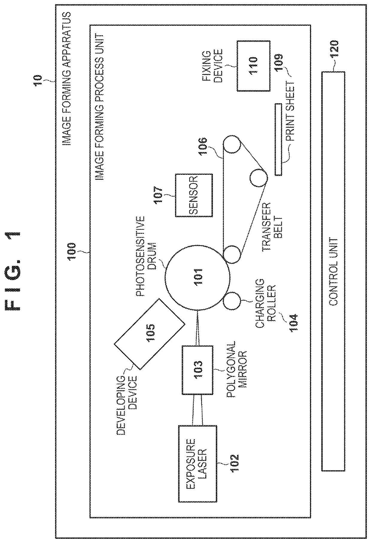
[0021]FIG. 1 is a view that exemplarily illustrates a configuration of an image forming apparatus 10 according to a first embodiment. The image forming apparatus 10 is configured by an image forming process unit 100 and a control unit 120.

[0022]The image forming process unit 100 is configured by a photosensitive drum 101 as an image carrier, an exposure laser 102, a polygonal mirror 103, a charging roller 104, a developing device 105, a transfer belt 106, a sensor 107, and a fixing device 110.

[0023]An outline regarding a series of processes for image forming by the image forming process unit 100 will be given. Firstly, the surface of the photosensitive drum 101 is charged by the charging roller 104, and the exposure laser 102 irradiates, via the polygonal mirror 103, the photosensi...

second embodiment

[0057]In the second embodiment, description is given regarding a method for switching control in a stepwise fashion. More specifically, a time period for PI (proportional-integral) control in accordance with reading of a motor current value is provided between a time period for forced commutation control and a time period for sensorless vector control in the first embodiment. Note that description is omitted for configurations similar to those in the first embodiment (FIG. 1 through FIG. 6).

[0058]

[0059]FIG. 7 is a view for describing a control mode of the motor in the second embodiment. A graph 700a illustrates timings of each process in “forced commutation control” which is a first control. A graph 700b illustrates timings of each process in “PI control” which is a second control. Note that description is omitted for sensorless vector control as it is the same as in the first embodiment (the graph 600a).

[0060]“Forced commutation control” is a control method for making a control per...

third embodiment

[0065]In the third embodiment, description is given regarding another method for switching control in a stepwise fashion. More specifically, a time period for “PI control+α” is provided between the time period for PI control and the time period for sensorless vector control in the second embodiment. Here, the “α” indicates one or more extra processing. Note that description is omitted for configurations similar to that in the embodiments described above (FIG. 1 through FIG. 7).

[0066]FIG. 8 is a view for describing a control mode of the motor in the third embodiment. A graph 800a illustrates timings of each process in “PI control” which is a second control, and is similar to the graph 700b. A graph 800b illustrates timings of each process in “PI control+α” which is a third control. Note that description is omitted for sensorless vector control as it is the same as in the first embodiment (the graph 600a).

[0067]As described above, “PI control” is a control method for shortening a cont...


PUM


Abstract

In order to shorten an activation time while realizing high accuracy motor control, a motor control apparatus operable to control a motor is provided. The apparatus comprises: a first drive control unit configured to drive the motor by forced commutation control; a second drive control unit configured to drive the motor by vector control; and a control unit configured to control to drive the motor by one of the first drive control unit and the second drive control unit. A first control period which is a control period in which the first drive control unit controls the motor is shorter than a second control period which is a control period in which the second drive control unit controls the motor.

Description

BACKGROUND OF THE INVENTIONField of the Invention[0001]The present invention relates to control of a motor.Description of the Related Art[0002]In a laser beam printer, a brushless DC motor or the like is used for driving of a photosensitive drum or a transfer belt. Typically, a brushless DC motor has a three-phase (a U phase, a V phase, and a W phase) stator, and the motor is caused to rotate by controlling voltages applied to these phases. At this point, a rotation speed that changes in accordance with a load or the like is detected and fed back to control to realize a stable rotation speed.[0003]Conventionally, the rotation speed is measured using a Hall sensor or the like, but in recent years, a method (sensorless vector control) for estimating rotation speed from current values for the three phases without using a sensor, and then performing vector control has been widely used (for example, Japanese Patent Laid-Open No. 2015-213398). However, to estimate a rotation speed without...

Claims


Application Information

Patent Timeline
Patent Type & Authority Patents(United States)
IPC IPC(8): H02P21/18H02P25/03H02P21/00
CPCH02P21/18H02P21/0003H02P25/03H02P21/24H02P21/34H02P6/21
Inventor AOKI, KUNITOSHIASHIDA, JUMPEI
Owner CANON KK
Why Eureka
Try Eureka