Electromagnetic actuator

a technology of electromagnetic actuators and actuators, applied in the direction of electromagnetic relay details, electromagnets, relays, etc., can solve the problems of large amount of electric power, limited power and energy storage capacity of control devices, and small electrical activation energy available, so as to shorten the activation time, reduce airborne energy, and reduce electrical activation energy

Inactive Publication Date: 2013-01-31
BENTELER AUTOMOBILTECHNIK GMBH
View PDF8 Cites 19 Cited by
  • Summary
  • Abstract
  • Description
  • Claims
  • Application Information

AI Technical Summary

Benefits of technology

[0010]As a result of the moveably supported components and the electrical freewheel circuit, the electromagnetic actuator according to the invention reduces sound emission which otherwise occurs due to the mechanical stress caused by the pulsating quiescent current in the conductors of the electromagnet under the influence of a permanent magnetic field. The aforedescribed structural features also reduce the electrical voltage in the electromagnet induced by the change in the magnetic flux.
[0047]In summary, an arbitrary combination and permutation of the aforedescribed embodiments of the electromagnetic actuator according to the invention advantageously reduces the electrical activation energy and / or shortens the activation time, as well as reduces airborne and structure-born sound emission compared to conventional electromagnetic actuators. In addition, the electromagnetic actuator according to the invention has more reliable release properties, and can be monitored with a quiescent current and can hence also be used for safety-relevant purposes. The electromagnetic actuator according to the invention is also more robust with respect to electromagnetic interferences, mechanical interferences as well as climate or environmental effects. Due to the electrical connection line with freewheel circuit and / or energy charge circuit, the effectiveness of the electromagnetic actuator is enhanced and consequently loss-related heat or sound emission is reduced. In particular, sounds caused by reaction forces in the magnet due to sudden changes of the electric current or of the magnetic flux can be prevented with the structure of the electromagnetic actuators according to the invention. In addition, the electromagnetic actuator according to the invention is reversible and compatible with, or can be adapted with the aforementioned electrical components to already existing electrical interfaces or control devices, for example the control devices for restraint systems for occupant protection in motor vehicles.

Problems solved by technology

Due to limited onboard power capacity in the vehicle, only a small electrical activation energy is available compared to the motion energy to be released for controlling the actuator.
The power and energy storage capacity of the control devices, however, is limited so that for controlling an actuator which consumes a comparatively large amount of electric power compared to the capacity of the control device, a power amplifier or a relay must be connected between the control device as energy supplier and the actuator as energy converter.

Method used


Image

  • Electromagnetic actuator
  • Electromagnetic actuator
  • Electromagnetic actuator

Examples


Embodiment Construction

[0056]Throughout all the figures, same or corresponding elements may generally be indicated by same reference numerals. These depicted embodiments are to be understood as illustrative of the invention and not as limiting in any way. It should also be understood that the figures are not necessarily to scale and that the embodiments are sometimes illustrated by graphic symbols, phantom lines, diagrammatic representations and fragmentary views. In certain instances, details which are not necessary for an understanding of the present invention or which render other details difficult to perceive may have been omitted.

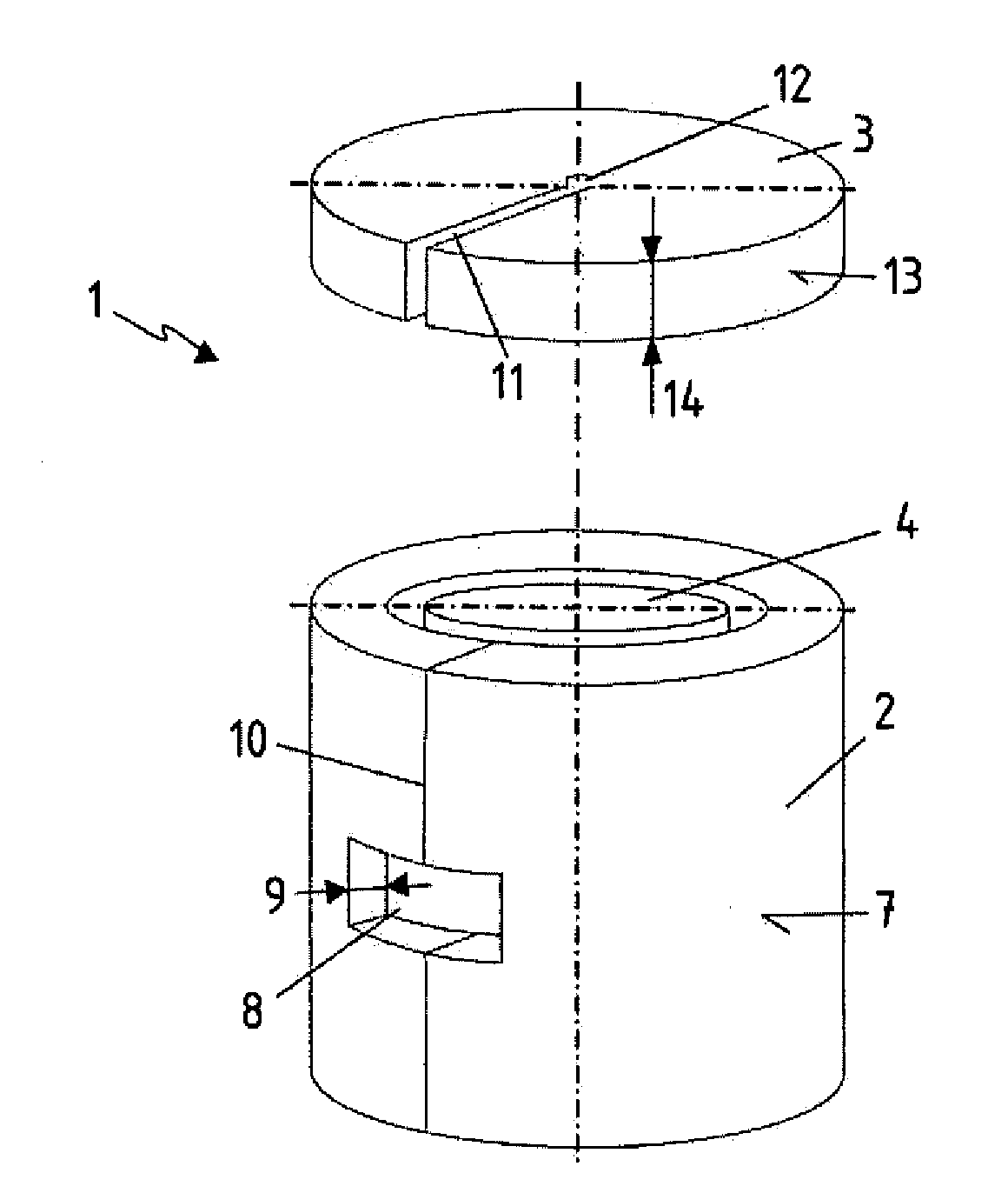
[0057]Turning now to the drawing, and in particular to FIG. 1, there is shown an electromagnetic actuator 1 formed of a cylindrical yoke 2, an armature 3 and an insert 4 coaxially arranged in the yoke 2. The insert 4 is here formed substantially from anisotropic permanent magnets 5 (not shown in detail) and an electromagnet 6. According to the invention, the yoke 2 has an op...


PUM

PropertyMeasurementUnit
thicknessaaaaaaaaaa
thicknessaaaaaaaaaa
thicknessaaaaaaaaaa

Abstract

An electromagnetic actuator operating like a holding magnet includes an anisotropic permanent magnet connected with a ferromagnetic yoke, an electromagnet and a ferromagnetic armature that is movable relative to the electromagnet. The yoke is cup-shaped and has a circular, elliptical or polygonal cross-section to reduce magnetic stray flux. All the aforementioned components are arranged coaxially with respect to a column-shaped core. The periphery of the yoke includes at least one opening configured for passage of the electrical conductors controlling the electromagnet. The opening also enables pressure equalization and vapor diffusion between the interior space of the actuator and the environment. The opening is oriented in the magnetic flux direction and is constructed to reduce eddy currents. The actuator also includes components forming an electrical freewheel circuit or an electrical energy store circuit.

Description

CROSS-REFERENCES TO RELATED APPLICATIONS[0001]This application claims the priority of German Patent Application, Serial No. 10 2011 052 173.9, filed Jul. 27, 2011, pursuant to 35 U.S.C. 119(a)-(d), the content of which is incorporated herein by reference in its entirety as if fully set forth herein.BACKGROUND OF THE INVENTION[0002]The present invention relates to an electromagnetic actuator, in particular for holding and releasing movable parts in motor vehicles.[0003]The following discussion of related art is provided to assist the reader in understanding the advantages of the invention, and is not to be construed as an admission that this related art is prior art to this invention.[0004]Electromagnetic actuators are known from their use in motor vehicles, in particular for operating seats, head rests, engine hoods, fuel tank caps, trunk lids, flaps, doors, convertible roofs and also devices protecting passengers from the effects of a collision. Due to limited onboard power capacit...

Claims


Application Information

Patent Timeline
Patent Type & Authority Applications(United States)
IPC IPC(8): H01H47/22H01H50/12H01F7/08
CPCH01F2007/1676H01F7/1646
Inventor RABE, FRANKSTEINHUBER, KATHRIN
Owner BENTELER AUTOMOBILTECHNIK GMBH
Why Eureka
Try Eureka