Passive optical network system and operating method thereof

optical network technology, applied in the field of configuration and operation of a passive optical network system, can solve the problems of reducing the net bandwidth that can be used for the transmission of signals from each onu, affecting the efficiency of the operation of the receiver circuit, etc., to achieve excellent bandwidth utilization efficiency, shorten the activation time of the pon, and increase the loss of optical fiber

Inactive Publication Date: 2008-08-07
HITACHI LTD
View PDF7 Cites 18 Cited by
  • Summary
  • Abstract
  • Description
  • Claims
  • Application Information

AI Technical Summary

Benefits of technology

[0008]The present invention has for an object to furnish a PON provided with a configuration resolving the aforementioned problems. That is to say that it has for an object to furnish a PON with excellent bandwidth utilization efficiency which is capable of receiving high-speed burst signals with an economical configuration and which can increase signals that can be transmitted from each ONU by eliminating or shortening the preambles from each ONU.
[0011]Further, since the level of the received optical signal becomes shorter because the loss in an optical fiber is greater for a signal coming from an ONU at a longer distance and it is received after a delay time proportional to the distance between the OLT and the ONU, it is acceptable to adopt a configuration in which, in the ranging process, optical signals from ONUs are expected with a large threshold value at the beginning of the ranging and optical signals are awaited by switching to a small threshold value in response to the lapse of time. According to this configuration, even if the plural preset threshold values are not tested without exception, it becomes possible to search appropriate threshold values in a short time from among the threshold value candidates for which the probability that the ranging succeeds is higher, so it becomes possible to shorten the activation time of the PON and the ONU.
[0012]According to the present invention, it is possible to provide a PON with excellent bandwidth utilization efficiency which can receive high-speed burst signals with an economical configuration and which can increase the signals which can be received from each ONU.

Problems solved by technology

That is to say that since there is a random variation in the transmission delay between each ONU and the OLT, there is a possibility, even if each ONU transmits a signal, that the optical signals output from each ONU on the trunk optical fiber collide and interfere with each other.
An economical supply of receiver circuits using devices able to handle these kinds of high transmission speeds is not straightforward.
However, if the preamble is made longer, the net bandwidth that can be used for the transmission of the signals from each ONU decreases and the bandwidth utilization efficiency drops.
That is to say that it ends up going against the objective of speeding up the system.
Also, in a configuration in which an amplifier such as in JP-A-2002-57627 is introduced, the configuration of the receiver circuit becomes a little easier, but there is no change in the need for receiver level measurements of the received optical signals, and since the configuration ends up becoming one using a costly amplifier using active components, it becomes difficult to attain the goal of making PONs economical.

Method used


Image

  • Passive optical network system and operating method thereof
  • Passive optical network system and operating method thereof
  • Passive optical network system and operating method thereof

Examples


Embodiment Construction

[0028]Below, a detailed description will be given, using the drawings, of a PON configuration and operation according to the present invention, citing as an example the operation of the configuration of a GPON defined in ITU-T Recommendation G984.

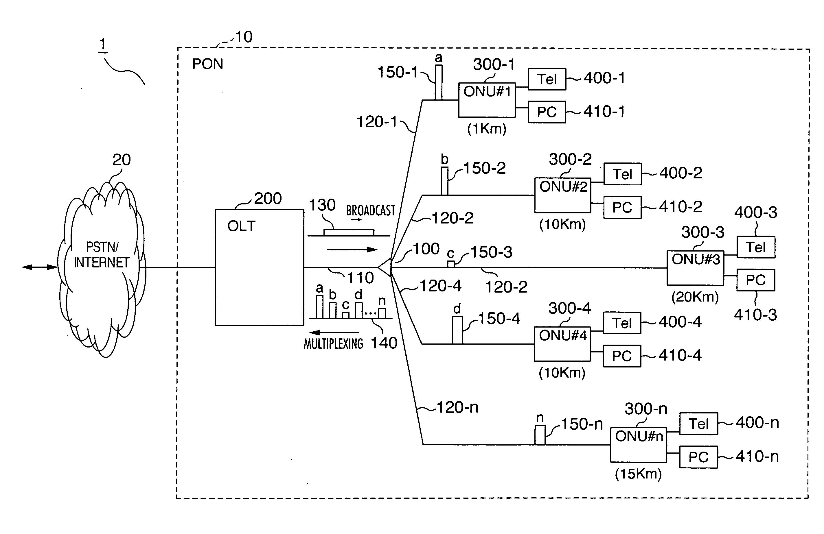
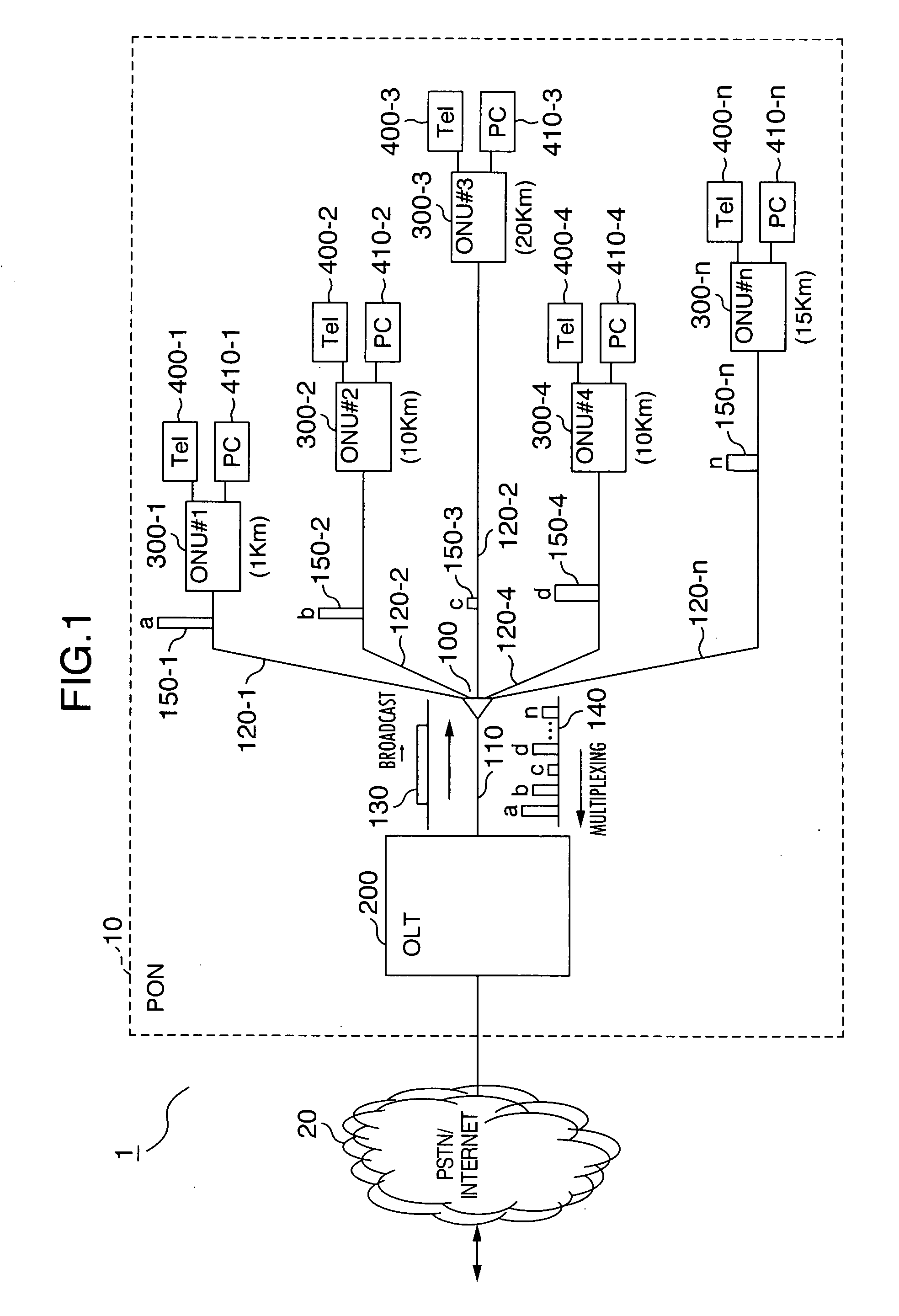
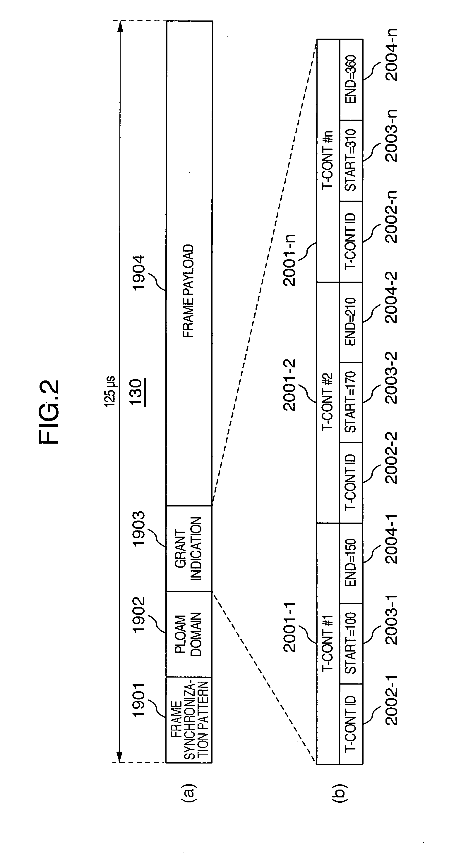
[0029]FIG. 1 is a network block diagram showing a configuration example of an optical access network using a PON. FIG. 2 and FIG. 3 are frame block diagrams respectively showing the configuration of an optical signal from an OLT to an ONU and an optical signal from an ONU to an OLT. Also, FIG. 4 is a sequence diagram showing an example of an operating sequence of a PON and FIG. 5 is an explanatory diagram showing a working example of a PON.

[0030]As shown in FIG. 1, an access network 1 is a network carrying out communication by connecting a public Switched Telephone network (PSTN) / Internet 20 (below sometimes called “host network”) and subscriber terminals (such as Tel 400 and PC 410) through a PON 10. PON 10 comprises an OLT 200 (below some...


PUM


Abstract

A Passive Optical Network system implementing a parent station capable of receiving high-speed burst signals transmitted from a plurality of subsidiary stations to a parent station, with excellent bandwidth utilization efficiency in the link from the stations to the parent. The system is provided with a configuration in which, when launched or an addition of a new subsidiary station, the parent stores threshold values appropriate for the received signals on the basis of the strength of the received signal for each subsidiary station, from among a plurality of preset threshold value candidates, and in response to the parent station's sending of a transmission grant with respect to each subsidiary station each time the subsidiary station transmitting optical signals changes, the stored threshold value corresponding to the subsidiary station is set in the receiver circuit.

Description

INCORPORATION BY REFERENCE[0001]The present application claims priority from Japanese application JP 2007-023652 filed on Feb. 2, 2007, the content of which is hereby incorporated by reference into this application.BACKGROUND OF THE INVENTION[0002]The present invention pertains to a configuration as well as an operating method of a Passive Optical Network system in which a plurality of subscriber connection devices share a transmission line.[0003]In order to transmit and receive high-capacity image signals or data via a communication network, the attainment of higher speeds and larger bandwidths is being advanced as well in the access network connecting the subscriber to the communication network, the introduction of a Passive Optical Network system (below called “PON”) defined in Recommendation G984.1-3 et cetera of the International Telecommunications Union (below called “ITU-T”) being aimed for. A PON is a system connecting an Optical Line Termination (below called “OLT”) connect...

Claims


Application Information

Patent Timeline
Patent Type & Authority Applications(United States)
IPC IPC(8): H04B10/13H04L12/44H04B10/27H04B10/272H04B10/524H04J14/00H04J14/02H04J14/08
CPCH04J3/1694H04Q2011/0079H04Q11/0067
Inventor KAZAWA, TOHRUOHIRA, MASAKIYAJIMA, YUSUKE
Owner HITACHI LTD
Why Eureka
Try Eureka