Piezoelectric valve

a technology of electric valves and valve bodies, applied in the direction of valves, generators/motors, service pipes, etc., can solve the problems of not being able to meet the needs of customers, braking of the block, and substantially complicated technical problems, and achieves efficient transmission, high torque, and easy regulation

Inactive Publication Date: 2007-05-31
ENGERY UNITED STATES DEPT OF +1
View PDF10 Cites 17 Cited by
  • Summary
  • Abstract
  • Description
  • Claims
  • Application Information

AI Technical Summary

Benefits of technology

[0015] When the valve is designed in accordance with the present invention, it is possible to easily regulate the output power, the frequency of operation and the “start-stop” or quazi-continuous mode of operation of the piezoelectric motor within wide limits by means of regulated sources of pulse current. Correspondingly, it is possible to provide high torques (up to 100 Nm), which in the majority of cases is sufficient to overcome adhesion of the turn plug to the saddle. Moreover, the high frequency of mechanical oscillations (up to 1 MHz) in,the form of radially directed standing acoustic waves provides a fast activation of the valve during transition between the positions “open” and “closed” of not more than 0.5 sec, and a possibility of positioning of the turn plug relative to the saddle at the level of several angular seconds.
[0016] Elastic ratchet pushers efficiently provide not only the transmission of torque from a wave shell, which pulsates radially in the same cycle with the mechanical vibrations of the piezoelectric generator, but also efficiently brake the turn plug in a given position during each interruption of the operation of the pulse current source.
[0017] In accordance with an additional feature of the present invention, the wave shell is provided with at least two resilient ratchet pushers which are located at substantially equal angular distances from one another. This reduces the probability of slippage of the ring-shaped rotor relative to the pushers during each start of the piezoelectric generator and facilitates the braking of the rotor and of the turn plug during each turning off of the pulse current source.

Problems solved by technology

Moreover, the braking of the block “classic electric motor-multi-stage reducer” with fixation of the output shaft of the reducer and of the turnable valve body of the valve connected to it, is a substantially complicated technical problem.
However, it is not acceptable when the valve must provide a cutoff of a raw material supply, for example ethylene into an explosion-prone apparatus for synthesis of polyethylene at a high pressure about 250 KPa.
Furthermore, the block “classic electric motor-multi-stage reducer” even if it has a significant frictional interaction between kinematic links of the reducer, can not provide by itself the accuracy of angular positioning of the valve bodies less than 3°.
Therefore, the valve devices are usually provided with complicated and expensive control means.
Therefore the introduction of the cumbersome multi-stage mechanical transmission between the output shaft of the pneumatic motor and the rod of the valve body significantly increases the mass and size of the motorized valve, increases the time of triggering which usually exceeds 10 seconds, and, due to inevitable gaps does not allow to position the turnable valve body relative to the seat with an angular accuracy less than 10.

Method used


Image

  • Piezoelectric valve
  • Piezoelectric valve

Examples


Embodiment Construction

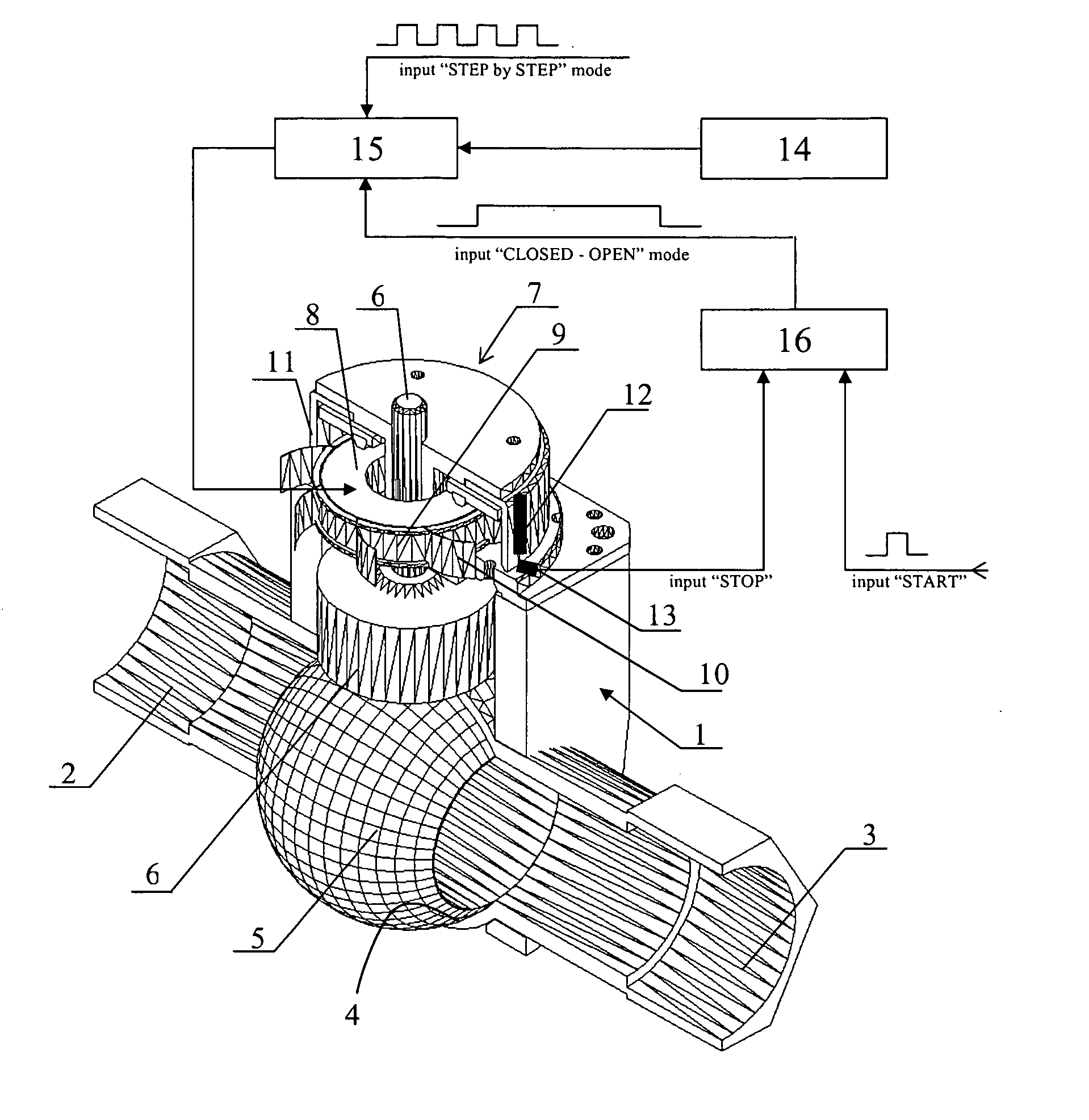
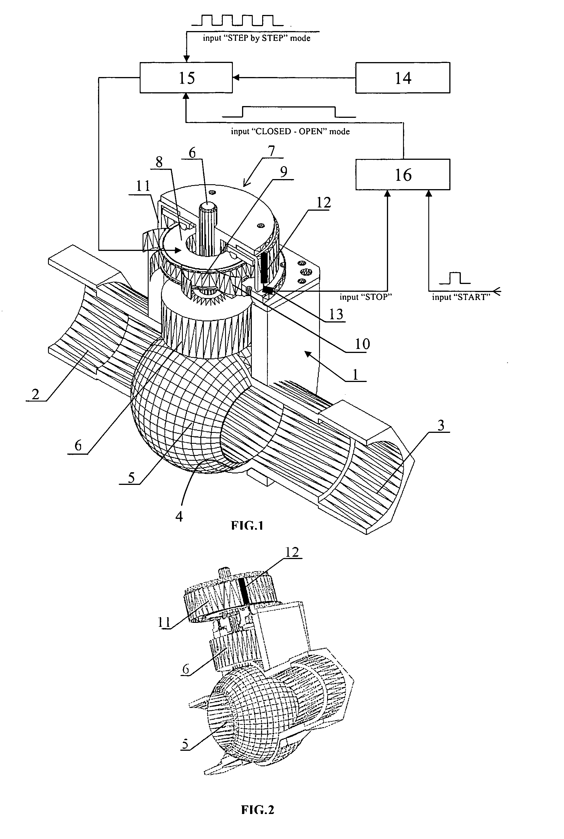
[0026] A valve in accordance with the present invention has a hollow throughgoing casing which is identified with reference numeral 1 and has an input tube 2 and an outlet tube 3 for connection to a pipeline. It further has an axis-symmetrical saddle 4 which is fixedly arranged inside the hollow case 1, and can be formed of one piece with the latter. The saddle 4 can be cylindrical, conical, or in particular spherical as shown in the drawings.

[0027] The valve further has a turn plug which is identified as a whole with reference numeral 5. It can be cylindrical, conical, or in particular spherical, as shown in the drawings. It is placed on the saddle 4, and in its upper part is provided with a rod 6. The rod 6 can be formed as a stepped rod. A drive for turning of the turn plug 5 is based on a piezoelectric motor and identified with reference numeral 7.

[0028] The piezoelectric motor 7 has a ring-shaped piezoelectric generator 8 which generates radially directed standing acoustic va...


PUM


Abstract

A motorized valve has a hollow case having an input and output tubes, a saddle connected with the hollow case, a turn plug cooperating with the saddle, and a piezoelectric drive to turn the turn plug, the piezoelectric drive including a piezoelectric generator of radially directed standing acoustic waves, which is connected with the hollow case and is connectable with a pulse current source, and a rotor operatively connected with the piezoelectric generator and kinematically connected with the turn plug so as to turn the turn plug when the rotor is actuated by the piezoelectric generator.

Description

PRIORITY CLAIM [0001] Priority is claimed from the Ukrainian patent application filed Nov. 29, 2005, Ser. No. 200511316. BACKGROUND OF THE INVENTION [0002] The present invention relates to fast-acting motorized valves with axis-symmetrical seats and turnable (cylindrical, conical, and preferably spherical) valve bodies. Such valves are designed for accurate regulation of flows of arbitrary flow media based on liquids and / or gasses and for closing / opening of vacuum lines. [0003] Valves with turnable valve bodies and manual drives for their turning are known. Such valves are widely used in household, laboratory and industrial distribution networks for gas and water supply, for closing and opening of corresponding pipelines and regulation of gas and liquid supplies in the cases when an operator can manually turn the valve body, and fast activation of the valve and angular accuracy of positioning of the valve body in the seat are not critical parameters. [0004] However, in energy genera...

Claims


Application Information

Patent Timeline
Patent Type & Authority Applications(United States)
IPC IPC(8): F16K37/00
CPCF16K31/004F16K31/042Y10T137/2196Y10T137/8242
Inventor PETRENKO, SERHIY FEDOROVICH
Owner ENGERY UNITED STATES DEPT OF
Why Eureka
Try Eureka