
Process for determining viability of test microorganisms of biological indicator and sterilization detection device for determining same

a biological indicator and viability technology, applied in the field of process for determining the viability of biological indicators, can solve the problems of inconvenient 24 to 72 hour holding period for sterility verification, cost and inefficiency, and achieve the effect of reducing the time in which this determination can be mad

Active Publication Date: 2021-01-26
AMERICAN STERILIZER CO
View PDF166 Cites 0 Cited by
  • Summary
  • Abstract
  • Description
  • Claims
  • Application Information

AI Technical Summary

Benefits of technology

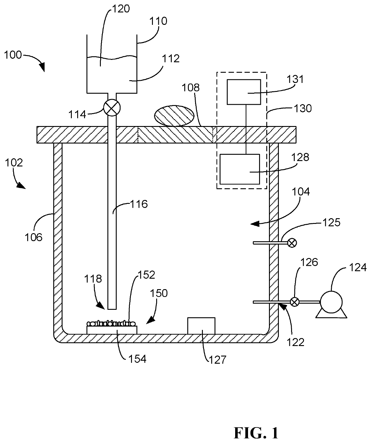
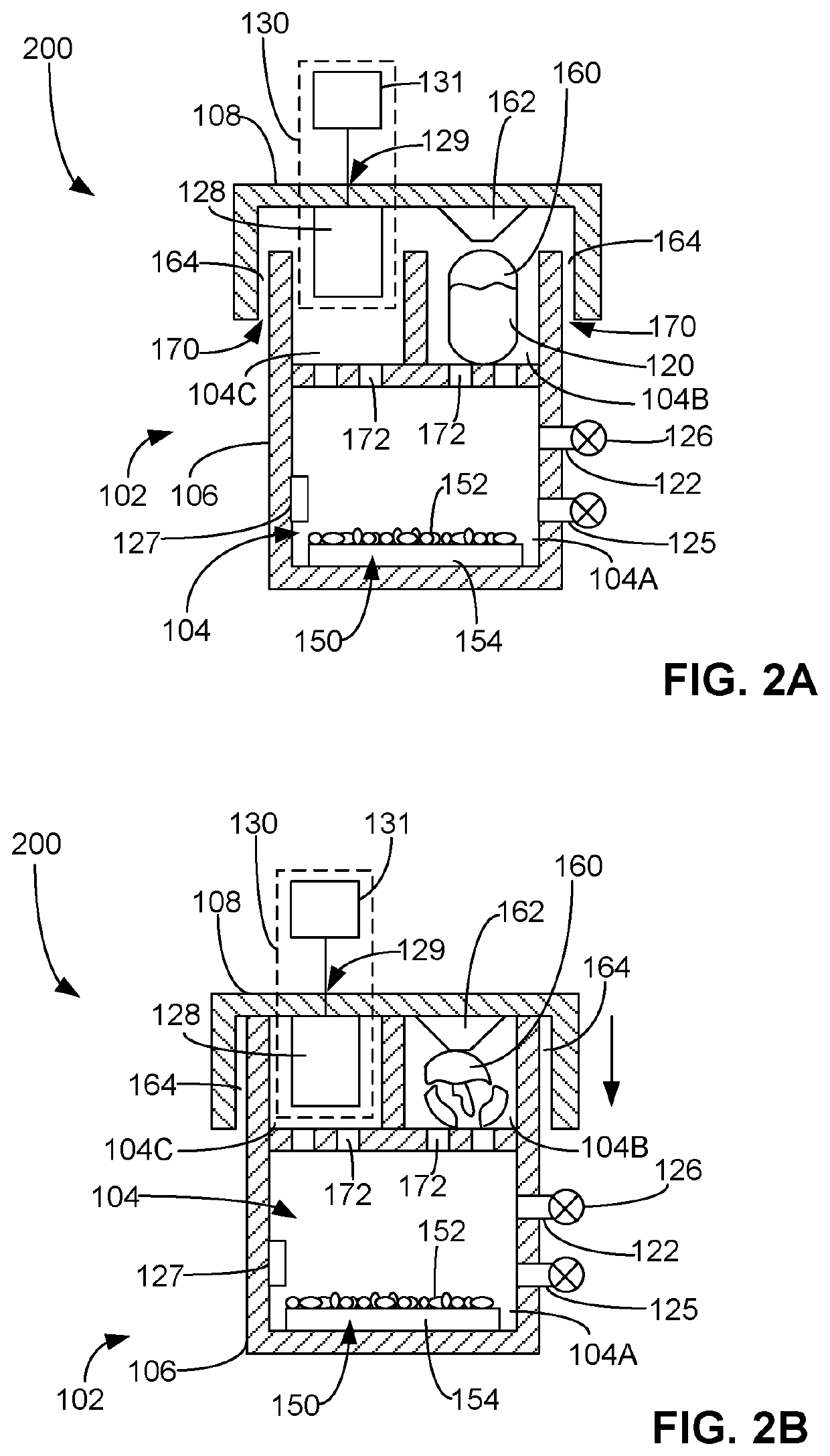
The patent text describes a process for determining the effectiveness of sterilizing equipment and articles in a short period of time. The process involves exposing a biological indicator containing test microorganisms to a sterilization medium and then detecting the presence or absence of a gaseous reaction product produced by the indicator. This gaseous reaction product indicates the presence or absence of viable test microorganisms. The process can be performed using a resistive sensor and can be used in health care facilities and other settings where sterilized equipment is used quickly. The use of the biological indicator allows for a direct approach to assay the lethality of the sterilization process.

Problems solved by technology

A problem with this process relates to the fact that many users of sterilized articles, such as health care facilities and the like, have limited resources and may reuse the “sterilized” articles within 24 to 72 hours and sometimes immediately.
In such settings, the 24 to 72 hour holding period for sterility verification may be impractical, costly and inefficient.
Thus, a problem in the art relates to determining the efficacy of a sterilization process within a short period of time.

Method used


Image

  • Process for determining viability of test microorganisms of biological indicator and sterilization detection device for determining same
  • Process for determining viability of test microorganisms of biological indicator and sterilization detection device for determining same
  • Process for determining viability of test microorganisms of biological indicator and sterilization detection device for determining same

Examples


Embodiment Construction

[0021]All ranges and ratio limits disclosed in the specification and claims may be combined in any manner. It is to be understood that unless specifically stated otherwise, references to “a,”“an,” and / or “the” may include one or more than one, and that reference to an item in the singular may also include the item in the plural.

[0022]The phrase “and / or” should be understood to mean “either or both” of the elements so conjoined, i.e., elements that are conjunctively present in some cases and disjunctively present in other cases. Other elements may optionally be present other than the elements specifically identified by the “and / or” clause, whether related or unrelated to those elements specifically identified unless clearly indicated to the contrary. Thus, as a non-limiting example, a reference to “A and / or B,” when used in conjunction with open-ended language such as “comprising” can refer, in one embodiment, to A without B (optionally including elements other than B); in another em...


PUM


Abstract

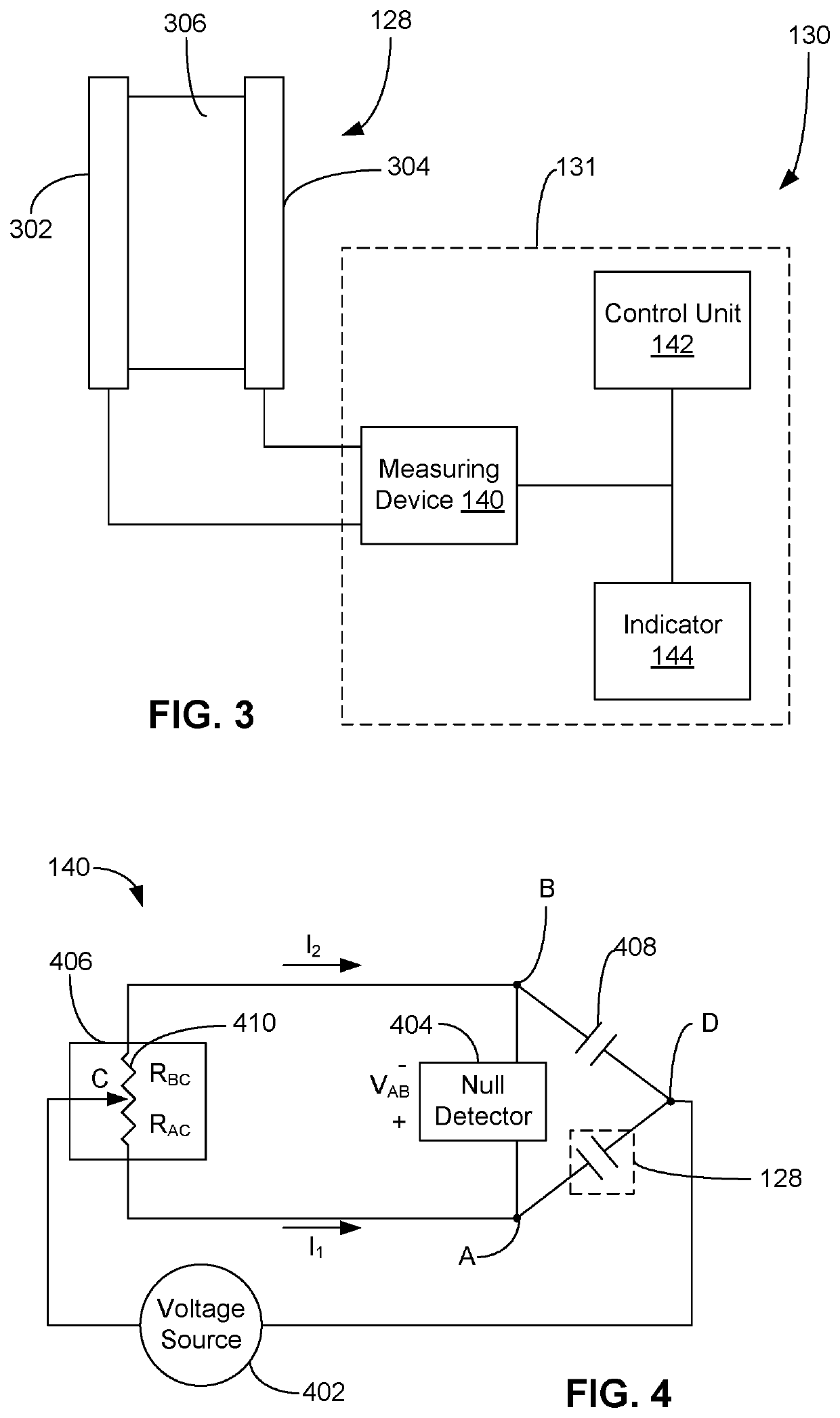
A process for determining the viability of a biological indicator includes exposing the biological indicator to a viability detection medium, the biological indicator including test microorganisms, the exposing the biological indicator to the viability detection medium producing a gaseous reaction product when one or more of the test microorganisms are viable. The presence or absence of the gaseous reaction product produced by the biological indicator combined with the viability detection medium is detected with a sensing device, the sensing device comprising a resistive sensor, wherein the presence of the gaseous reaction product indicates the presence of viable test microorganisms and the absence of the gaseous reaction product indicates the absence of viable test microorganisms. A sterilization detection device includes a container configured to contain the biological indicator, a viability detection medium, and the sensing device.

Description

TECHNICAL FIELD[0001]The present disclosure relates to a process for determining the viability of a biological indicator. A sterilization detection device may utilize said process for evaluating the efficacy of a sterilization process.BACKGROUND[0002]Biological indicators, which typically include a carrier and test microorganisms (e.g., spores) deposited on the carrier, are used for evaluating the efficacy of sterilization processes. The biological indicator is placed in a sterilization chamber and subjected to a sterilization process along with the load intended for sterilization (e.g., a medical device). Following the sterilization process, the biological indicator is exposed to a growth media and incubated for the purpose of determining if any of the test organisms are viable. A successful sterilization process is indicated by a complete inactivation (no outgrowth) of the test organisms. An unsuccessful sterilization process is indicated by an incomplete inactivation (outgrowth d...

Claims


Application Information

Patent Timeline
Patent Type & Authority Patents(United States)
IPC IPC(8): C12Q1/22G01N27/12C12M1/12G01N33/497
CPCC12Q1/22G01N27/12C12M37/06G01N2033/4977G01N2333/32G01N2333/33G01N2333/908G01N27/04G01N33/4977
Inventor FRANCISKOVICH, PHILLIP P.CENTANNI, MICHAEL A.
Owner AMERICAN STERILIZER CO
Learn More