Form measuring apparatus

a technology of measuring apparatus and spherical plate, which is applied in the direction of electric/magnetic roughness/irregularity measurement, electric/magnetic measuring arrangement, instruments, etc., can solve the problems of difficult positioning of structural components and substantial change in detection sensitivity, and achieve the resolution and measurement range that are desired, and the stress is greater.

Active Publication Date: 2021-01-26
MITUTOYO CORP
View PDF16 Cites 1 Cited by
  • Summary
  • Abstract
  • Description
  • Claims
  • Application Information

AI Technical Summary

Benefits of technology

[0005]An advantage of the present invention provides a contact-type form measuring apparatus that is capable of achieving a desired resolution and measurement range simply.
[0006]A form measuring apparatus according to the present invention includes a base; an arm capable of swinging relative to the base; a coupling member coupling the base and the arm, and having a deformation region that is capable of elastic deformation between the base and the arm; and a distortion detecting element installed in the deformation region.
[0007]With such a configuration, a stylus mounted to the arm can slide along a surface of a work piece. When the stylus displaces along the surface of the work piece, the arm swings and stress from the arm swinging is applied to the coupling member, and the deformation region of the coupling member undergoes elastic deformation. An amount of deformation of the deformation region corresponds to an amount of displacement of the stylus. Accordingly, in the form measuring apparatus according to the present invention, based on the amount of deformation of the deformation region that is detected by the distortion detecting element, the amount of displacement of the stylus can be detected, and thereby a surface form of the work piece can be measured.
[0008]In this example, the amount of deformation of the deformation region of the coupling member differs depending on a position in a coupling direction of the base and the arm within the deformation region. Specifically, in the deformation region of the coupling member, the closer the position is to the base in the coupling direction of the base and the arm, the greater the stress that is applied. Thus, the deformation region deforms more the closer a location is to the base, and deforms less the closer the location is to the arm. Therefore, the placement of the distortion detecting element within the deformation region affects the detection sensitivity for detecting displacement of the stylus.
[0009]For example, when the distortion detecting element is installed at a location in the deformation region that is closer to the base, even a slight displacement of the stylus can be detected as deformation of the coupling member, and therefore the detection sensitivity for displacement of the stylus is increased. Thus, a high-resolution can be achieved in the form measuring apparatus of the present invention. Meanwhile, when the distortion detecting element is installed at a location in the deformation region that is closer to the arm, deformation of the coupling member is unlikely to be detected for a slight displacement of the stylus, and therefore the detection sensitivity for displacement of the stylus is inhibited. Thus, the form measuring apparatus according to the present invention becomes capable of long stroke detection for displacement of the stylus, and its measurement range is broadened. Therefore, by adjusting the installation position of the distortion detecting element within the deformation region of the coupling member during manufacture or calibration of the form measuring apparatus according to the present invention, for example, a desired resolution and measurement range can be achieved simply.
[0010]In the form measuring apparatus according to the present invention, preferably, the coupling member is formed of an elastic material, and the form measuring apparatus further includes a distance adjustment mechanism that adjusts a distance between the base and the arm. With such a configuration, the coupling member is formed of an elastic material, and therefore a location on the coupling member that is located between the base and the arm creates the deformation region. Given this, by adjusting the distance between the base and the arm using the distance adjustment mechanism, the length of the deformation region in the coupling direction of the base and the arm is increased and decreased, and the amount of deformation of the deformation region relative to the amount of displacement of the stylus is modified. Thus, the detection sensitivity for the displacement of the stylus can be readily adjusted.

Problems solved by technology

However, in a differential transformer-type detection device of this kind, detection sensitivity can change substantially due to slight shifts in position of the structural components.
Therefore, positioning the structural components is difficult, and a great deal of design know-how is necessary to configure a form measuring apparatus having a desired resolution or measurement range.

Method used


Image

  • Form measuring apparatus
  • Form measuring apparatus
  • Form measuring apparatus

Examples


first embodiment

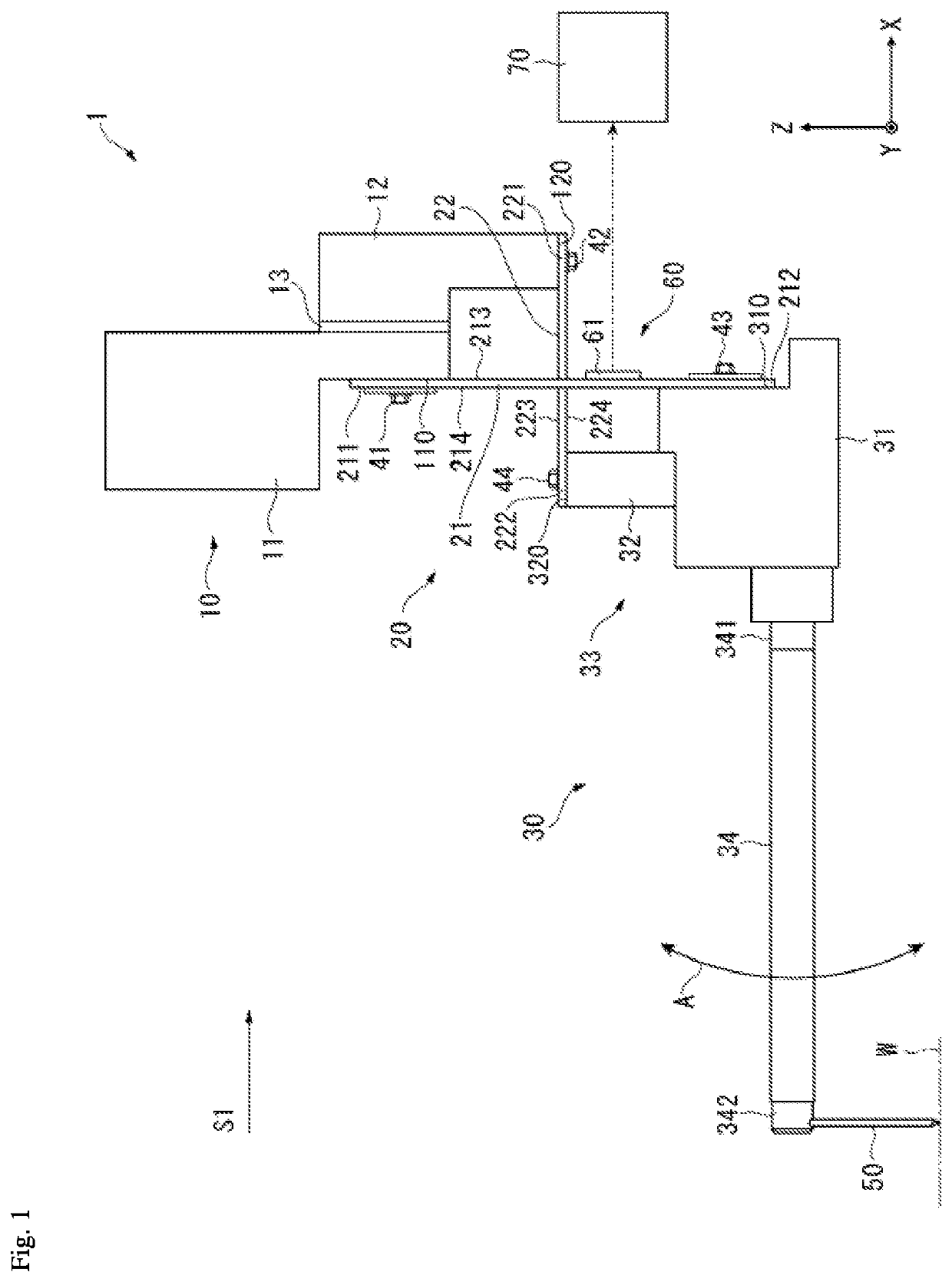
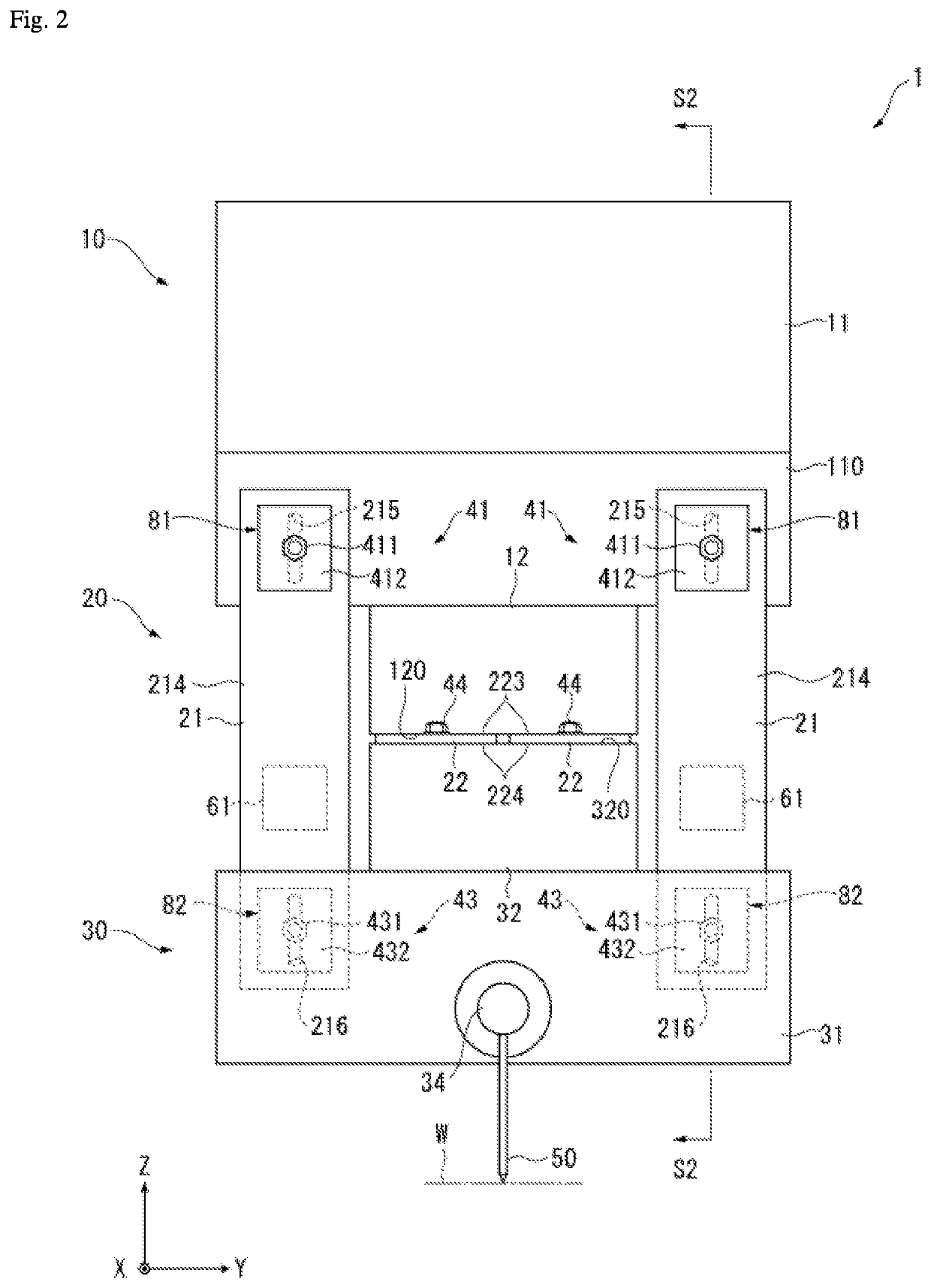
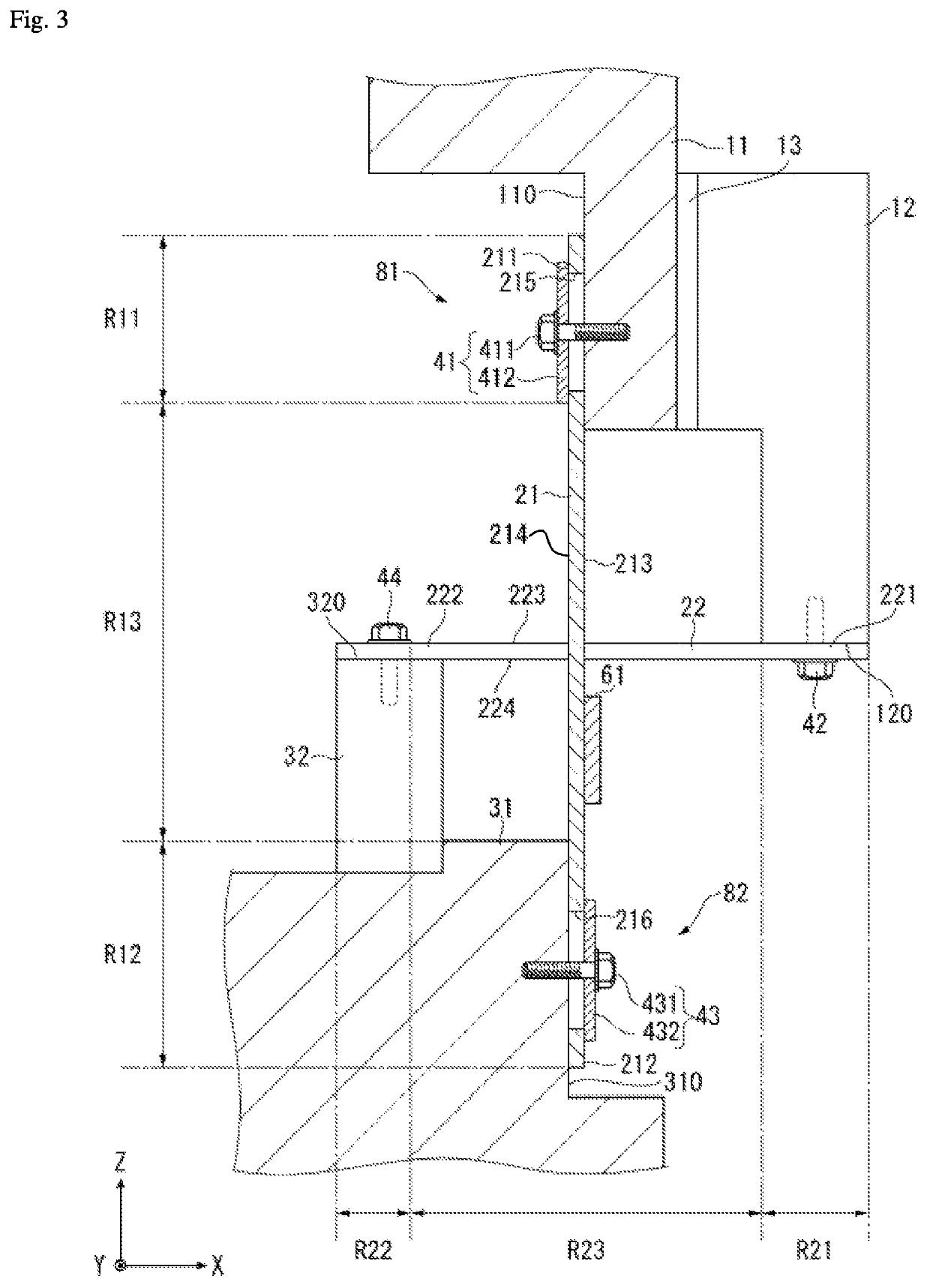
[0026]FIGS. 1 to 3 illustrate a first embodiment according to the present invention. A form measuring apparatus 1 uses a stylus 50 that is capable of sliding along a work piece W to measure a surface form of the work piece W. For example, the work piece W is arranged parallel to an XY plane (horizontal plane) and the form measuring apparatus 1 performs a measurement operation in which the stylus 50 is brought into contact with a surface of the work piece W, after which the stylus 50 is displaced relative to the work piece W in a direction parallel to the XY plane. Then, Z direction (perpendicular direction) displacement of the stylus 50 during the measurement operation is detected, whereby the surface form of the work piece W is measured.

[0027]An overall configuration of the form measuring apparatus 1 is described with reference to FIGS. 1 and 2. The form measuring apparatus 1 includes a base 10, a coupling member (coupler) 20, an arm 30, the stylus 50, and a distortion detector 60....

second embodiment

[0056]FIG. 4 illustrates a form measuring apparatus 2 according to a second embodiment of the present invention. The form measuring apparatus 2 has the same basic structure as the form measuring apparatus 1 according to the first embodiment, described above. Therefore, duplicative descriptions of shared components are omitted and only those components that are differentiated are described below.

[0057]In the present embodiment, a distortion detector 60A includes at least a pair (one pair in the present embodiment) of distortion detecting elements 62 and 63 that are provided to each of the plate springs 21 in the deformation region R13. The distortion detecting elements 62 and 63 are piezoelectric elements that are respectively arranged on the pair of surfaces 213 and 214 of the plate spring 21 and configure a pair having the plate spring 21 therebetween. The distortion detecting elements 62 and 63 configure bimorph-type piezoelectric elements for detection that are joined to each oth...

third embodiment

[0062]FIG. 5 illustrates a form measuring apparatus 3 according to a third embodiment of the present invention. The form measuring apparatus 3 has the same basic structure as the form measuring apparatus 1 according to the first embodiment, described above. Therefore, duplicative descriptions of shared components are omitted and only those components that are differentiated are described below.

[0063]In the present embodiment, a coupling member 20A includes one or a plurality of the plate springs 21 arranged so as to follow the Z direction. However, the coupling portion 20A does not include the plate spring 22 (see FIG. 1) which is arranged so as to follow the X direction in the first embodiment, and the second base portion 12, the second arm portion 32, and the like to which the plate spring 22 is fixed are omitted.

[0064]The form measuring apparatus 3 according to the present embodiment includes a block-shaped confining member (limiter or restrictor) 83 that is provided to the base ...


PUM


Abstract

A form measuring apparatus includes a base; an arm capable of swinging relative to the base; a coupler coupling the base and the arm, and having a deformation region that is capable of elastic deformation between the base and the arm; and a distortion detector installed in the deformation region. In the form measuring apparatus, a stylus is mounted to the arm and can slide along a surface of a work piece.

Description

CROSS-REFERENCE TO RELATED APPLICATIONS[0001]The present application claims priority under 35 U.S.C. § 119 of Japanese Application No. 2017-232532, filed on Dec. 4, 2017, the disclosure of which is expressly incorporated by reference herein in its entirety.BACKGROUND OF THE INVENTION1. Field of the Invention[0002]The present invention relates to a form measuring apparatus that measures a surface form of a work piece.2. Description of Related Art[0003]In order to measure a surface form of a work piece, a contact-type form measuring apparatus exists which slides a stylus along a surface of the work piece and detects deviation of the surface. For example, Japanese Patent Laid-open Publication No. 2014-167435 discloses a form measuring apparatus that includes an arm that rotates freely centered on a pivot point, a stylus that is mounted to a first end of the arm, and a detection device that detects displacement of a second end of the arm. In this form measuring apparatus, when the stylu...

Claims


Application Information

Patent Timeline
Patent Type & Authority Patents(United States)
IPC IPC(8): G01B5/28G01B5/20G01B7/34G01B5/00G01B5/30
CPCG01B5/201G01B5/0007G01B5/0009G01B5/20G01B5/28G01B7/34G01B5/30
Inventor SHIMAOKA, ATSUSHIHIDAKA, KAZUHIKO
Owner MITUTOYO CORP
Why Eureka
Try Eureka