
Projection optical system, exposure apparatus and method using the same

a technology which is applied in the field of projection optical system and exposure apparatus, can solve the problems of deformation of the surface shape of the optical system, difficulty in meeting the requirement of using, and the inability of the optical system to include any lenses, and achieve the effect of superior exposure performance and desired resolution

Inactive Publication Date: 2006-02-28
CANON KK
View PDF12 Cites 25 Cited by
  • Summary
  • Abstract
  • Description
  • Claims
  • Application Information

AI Technical Summary

Benefits of technology

[0008]Accordingly, it is an exemplified object of the present invention to provide a projection optical system, and an exposure apparatus and method, which may obtain desired resolution, and provide superior exposure performance.

Problems solved by technology

The recent trend has required that the resolution be a smaller value; however it is difficult to meet this requirement using only the increased NA, and the improved resolution expects use of a shortened wavelength.
No applicable glass materials have been proposed for the EUV light as exposure light, and a projection optical system could not include any lenses.
However, an area or slit used for exposure is a limited area that is apart from the optical axis, and one or more mirrors in the catoptric optical system receive exposure light locally or partially.
Such a mirror as locally receives the exposure light generates a temperature difference in its materials, deforms its surface shape, and deteriorates its optical performance.
However, the catoptric projection optical system proposed in Japanese Laid-Open Patent Application No. 11-243052 provides the cooling unit at the rear side of an unilluminated area and reflection surface of a mirror that uses only part for exposure, and thus the temperature difference generated in the mirror cannot be mitigated sufficiently.
After all, the surface shape changes and deteriorates the optical performance, and this system cannot obtain desired resolution.

Method used


Image

  • Projection optical system, exposure apparatus and method using the same
  • Projection optical system, exposure apparatus and method using the same
  • Projection optical system, exposure apparatus and method using the same

Examples


Embodiment Construction

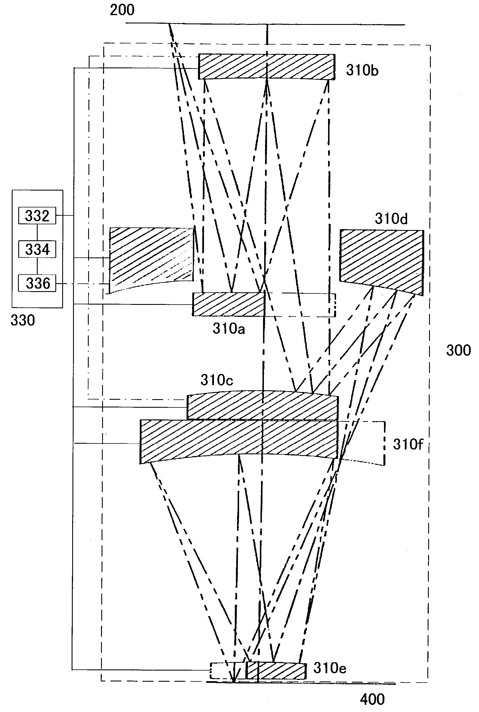
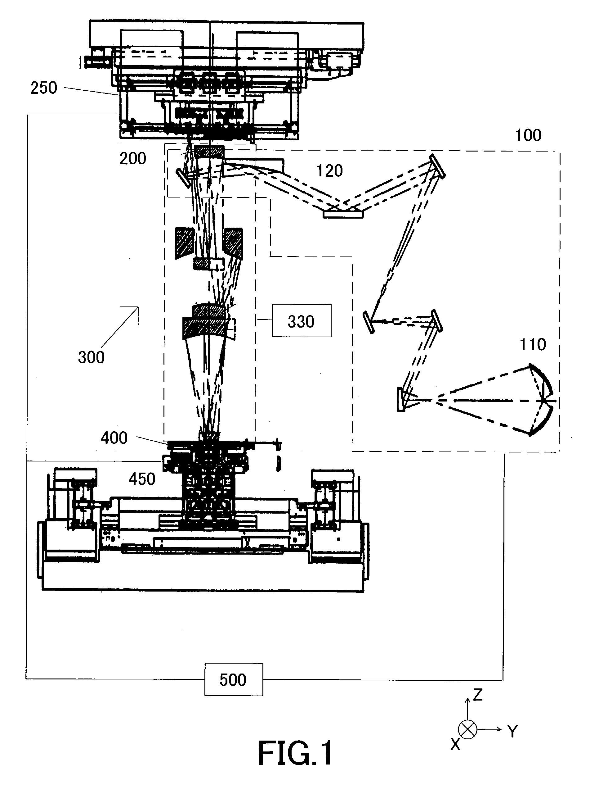
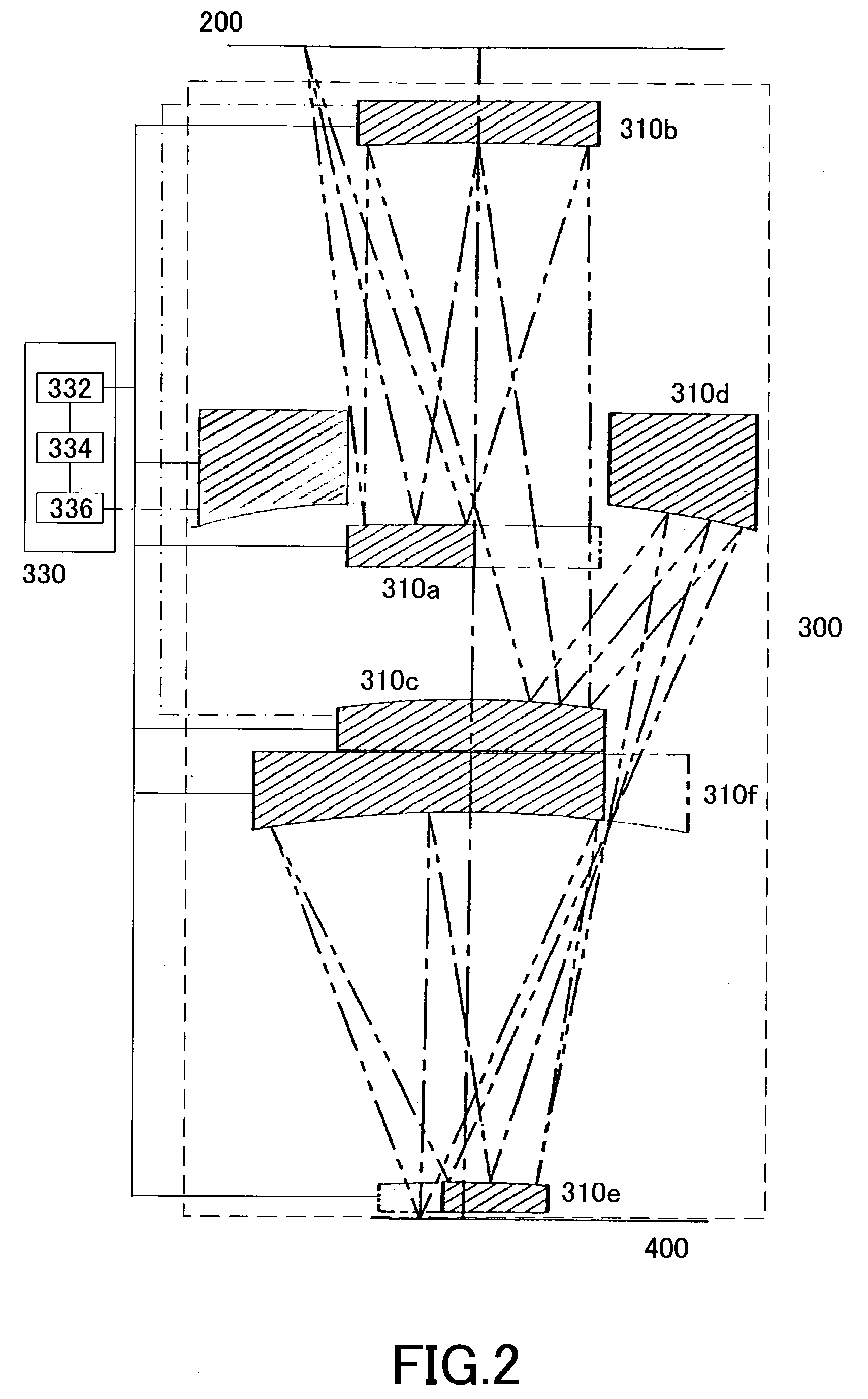
[0024]A description will now be given of a reflection type projection optical system 300 and an exposure apparatus 200 as one aspect of the present invention with reference to the accompanying drawings. The present invention is not limited to these embodiments and each element is replaceable within a scope that achieves the objects of the present invention. Here, FIG. 1 is a schematic structural view showing the exposure apparatus 1 of one aspect according to the present invention.

[0025]The exposure apparatus 1 includes, as shown in FIG. 1, an illumination apparatus 100, a mask 200, a projection optical system, a plate 400, and a controller 500.

[0026]The exposure apparatus 1 uses, as illumination light for exposure, an EUV ray (with a wavelength of, e.g., 13.4 nm) to exposes onto the plate 400 a circuit pattern formed on the mask 200, for example, in a step-and-repeat manner and step-and-scan manner. This projection exposure apparatus is suitable for a lithography process of a submi...


PUM

PropertyMeasurementUnit
sizeaaaaaaaaaa
sizeaaaaaaaaaa
wavelengthaaaaaaaaaa

Abstract

A projection optical system includes an optical element that includes and locally uses a reflective or refractive area that is substantially axially symmetrical around an optical axis, the optical element being rotatable around the optical axis.

Description

BACKGROUND OF THE INVENTION[0001]The present invention relates to an exposure apparatus for exposing an object, such as a single crystal substrate and a glass plate for a liquid crystal display (“LCD”). The present invention is especially suitable for an exposure apparatus that uses ultraviolet (“UV”) and extreme ultraviolet (“EUV”) light as an exposure light source.[0002]Along with the recent demand on smaller and lower profile electronic devices, a miniaturization of semiconductor devices to be mounted onto these electronic devices have been increasingly demanded. For example, a design rule for a mask pattern requires that an image with a size of a line and space (L & S) of less than 0.1 μm be extensively formed, and predictably, it will further move to a formation of circuit patterns of less than 80 nm in the future. L & S denotes an image projected to a wafer in exposure with equal line and space widths, and serves as an index of exposure resolution.[0003]A projection exposure a...

Claims


Application Information

Patent Timeline
Patent Type & Authority Patents(United States)
IPC IPC(8): G03B27/52G03B27/42G03B27/54G03B27/68G03F7/20H01L21/027
CPCG03B27/54G03F7/70891G03F7/706
Inventor SUMIYOSHI, YUHEISUZUKI, MASAYUKI
Owner CANON KK
Learn More