Form measuring apparatus
- Summary
- Abstract
- Description
- Claims
- Application Information
AI Technical Summary
Benefits of technology
Problems solved by technology
Method used
Image
Examples
first embodiment
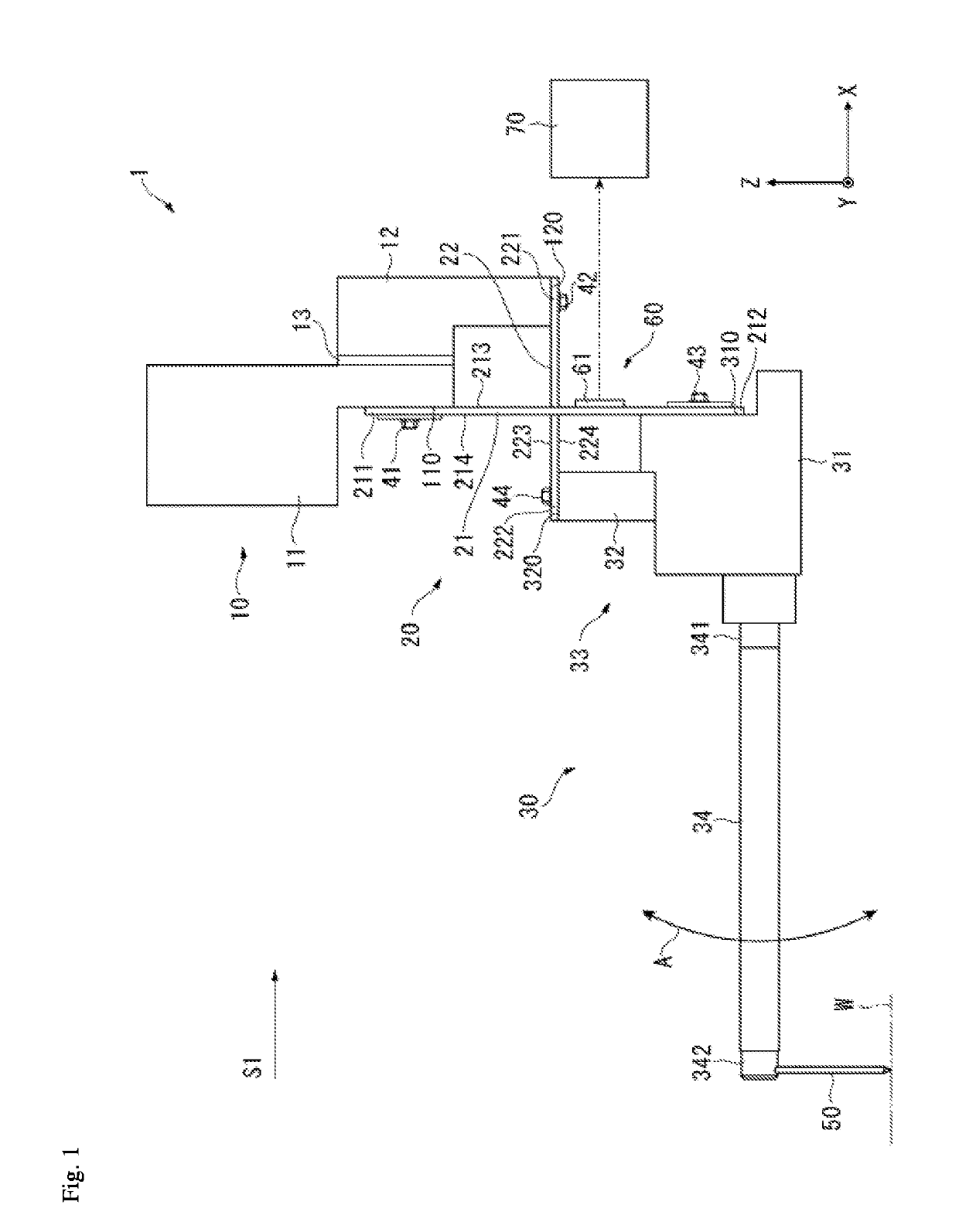
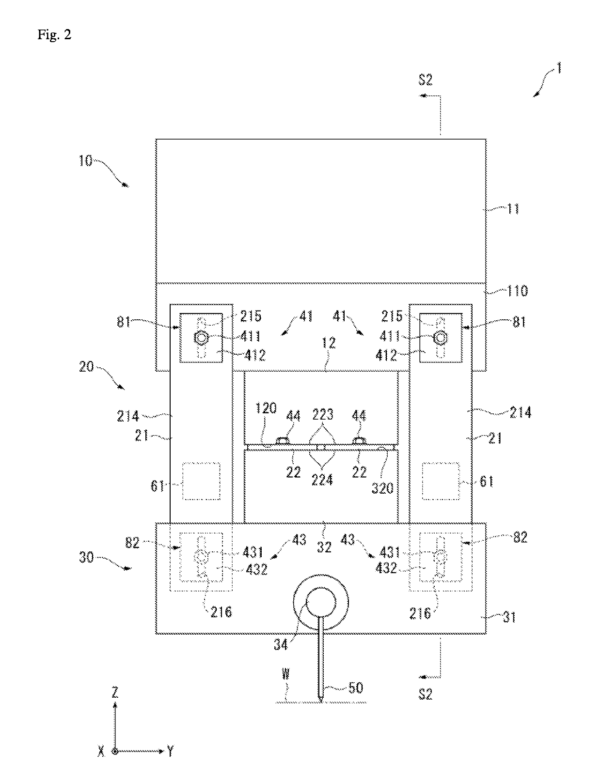
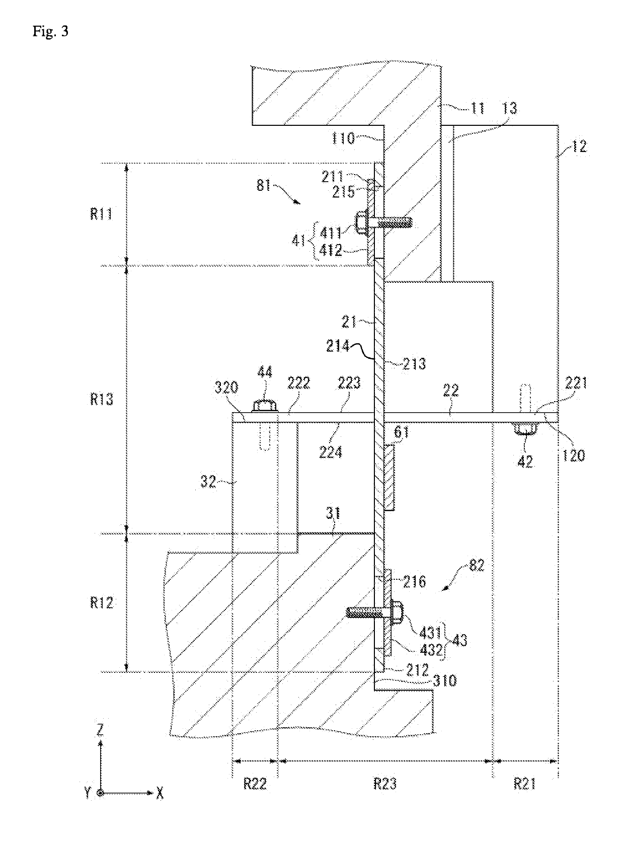
[0026]FIGS. 1 to 3 illustrate a first embodiment according to the present invention. A form measuring apparatus 1 uses a stylus 50 that is capable of sliding along a work piece W to measure a surface form of the work piece W. For example, the work piece W is arranged parallel to an XY plane (horizontal plane) and the form measuring apparatus 1 performs a measurement operation in which the stylus 50 is brought into contact with a surface of the work piece W, after which the stylus 50 is displaced relative to the work piece W in a direction parallel to the XY plane. Then, Z direction (perpendicular direction) displacement of the stylus 50 during the measurement operation is detected, whereby the surface form of the work piece W is measured.
[0027]An overall configuration of the form measuring apparatus 1 is described with reference to FIGS. 1 and 2. The form measuring apparatus 1 includes a base 10, a coupling member (coupler) 20, an arm 30, the stylus 50, and a distortion detector 60....
second embodiment
[0056]FIG. 4 illustrates a form measuring apparatus 2 according to a second embodiment of the present invention. The form measuring apparatus 2 has the same basic structure as the form measuring apparatus 1 according to the first embodiment, described above. Therefore, duplicative descriptions of shared components are omitted and only those components that are differentiated are described below.
[0057]In the present embodiment, a distortion detector 60A includes at least a pair (one pair in the present embodiment) of distortion detecting elements 62 and 63 that are provided to each of the plate springs 21 in the deformation region R13. The distortion detecting elements 62 and 63 are piezoelectric elements that are respectively arranged on the pair of surfaces 213 and 214 of the plate spring 21 and configure a pair having the plate spring 21 therebetween. The distortion detecting elements 62 and 63 configure bimorph-type piezoelectric elements for detection that are joined to each oth...
third embodiment
[0062]FIG. 5 illustrates a form measuring apparatus 3 according to a third embodiment of the present invention. The form measuring apparatus 3 has the same basic structure as the form measuring apparatus 1 according to the first embodiment, described above. Therefore, duplicative descriptions of shared components are omitted and only those components that are differentiated are described below.
[0063]In the present embodiment, a coupling member 20A includes one or a plurality of the plate springs 21 arranged so as to follow the Z direction. However, the coupling portion 20A does not include the plate spring 22 (see FIG. 1) which is arranged so as to follow the X direction in the first embodiment, and the second base portion 12, the second arm portion 32, and the like to which the plate spring 22 is fixed are omitted.
[0064]The form measuring apparatus 3 according to the present embodiment includes a block-shaped confining member (limiter or restrictor) 83 that is provided to the base ...
PUM
 Abstract
Description
Claims
Application Information
 - R&D
- Intellectual Property
- Life Sciences
- Materials
- Tech Scout
- Unparalleled Data Quality
- Higher Quality Content
- 60% Fewer Hallucinations
Browse by: Latest US Patents, China's latest patents, Technical Efficacy Thesaurus, Application Domain, Technology Topic, Popular Technical Reports.
© 2025 PatSnap. All rights reserved.Legal|Privacy policy|Modern Slavery Act Transparency Statement|Sitemap|About US| Contact US: help@patsnap.com


