
Display apparatus

a technology of display apparatus and display screen, which is applied in the direction of transducer diaphragms, electromechanical transducers, instruments, etc., can solve the problems of difficult to deliver the sound output of the sound device clearly to a user without disrupting, and the sound quality may deteriorate, so as to enhance enhance sound quality. , the effect of enhancing the quality of output sound

Active Publication Date: 2021-01-26
LG DISPLAY CO LTD
View PDF53 Cites 1 Cited by
  • Summary
  • Abstract
  • Description
  • Claims
  • Application Information

AI Technical Summary

Benefits of technology

[0011]Therefore, the inventors have recognized the above-described problems and have performed various experiments for developing a sound generator which is miniaturized for incorporation in display apparatuses and outputs enhanced sound. Through the various experiments, the inventors have developed a display apparatus having a new structure, which includes a sound generator that enhances the quality of output sound and is capable of being miniaturized, for example, for incorporation in display apparatuses of varying sizes and shapes.
[0012]An aspect of the present disclosure is to provide a display apparatus including a sound generator which enhances sound quality and is capable of being miniaturized.

Problems solved by technology

In this arrangement, sound quality may deteriorate, for example, due to an interference with sound reflecting on the wall and floor.
Thus, it is difficult to deliver the sound output from the sound device clearly to a user without disrupting his or her immersion experience.

Method used


Image

  • Display apparatus
  • Display apparatus
  • Display apparatus

Examples


first embodiment

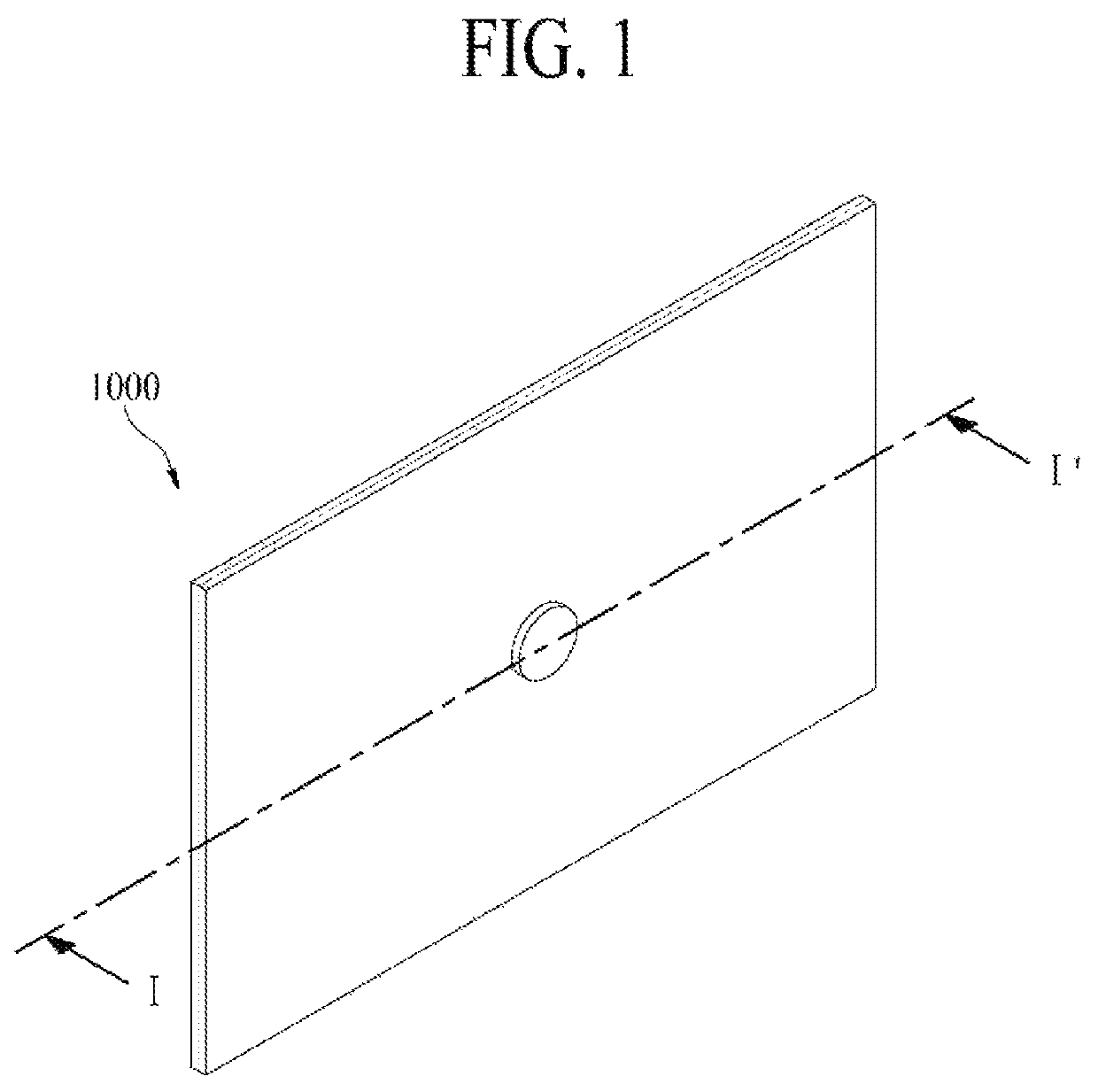
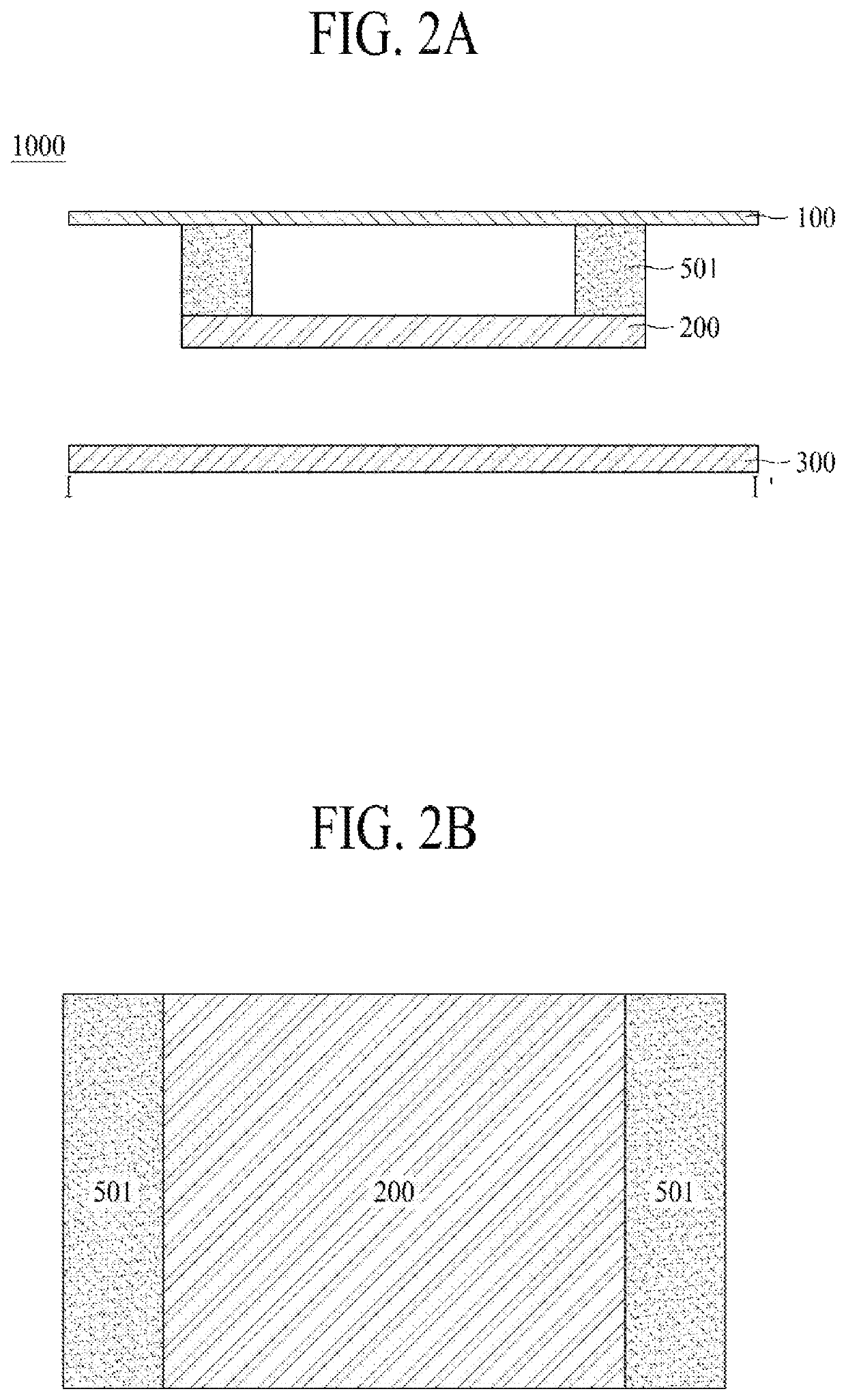
[0101]FIG. 2A is a cross-sectional view taken along line I-I′ of FIG. 1 and illustrates a display apparatus according to the present disclosure.

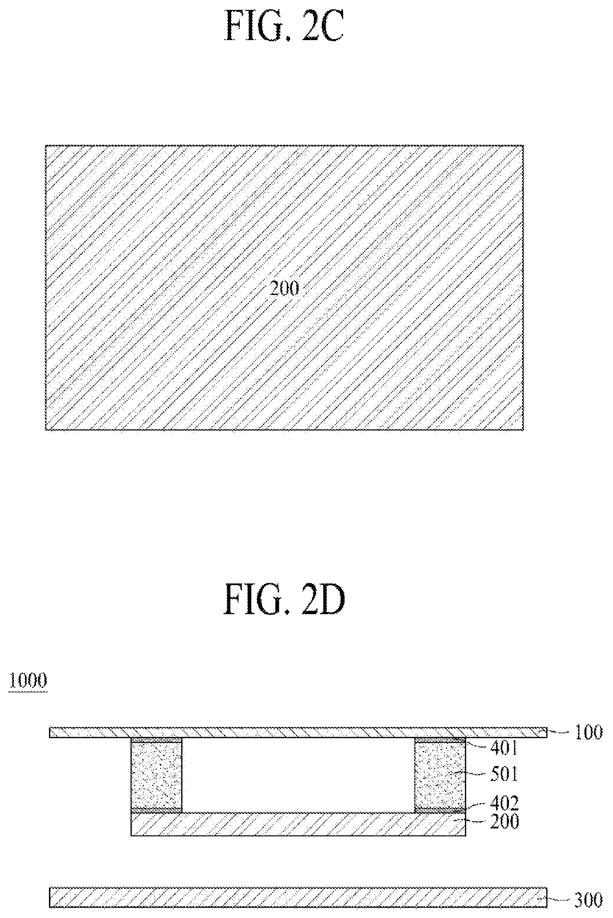
[0102]As shown in FIG. 2A, a supporting member 300 and a sound generator 200 may be on a rear surface of a display panel 100. Also, the sound generator 200 may be between the display panel 100 and the supporting member 300. Also, at least one vibration generation members 501 may be between the display panel 100 and the sound generator 200.

[0103]The at least one vibration generation member 501 may be between the display panel 100 and the sound generator 200 so that the sound generator 200 is not attached to a whole surface of the display panel 100. Therefore, a contact area between the sound generator 200 and the display panel 100 does not become a whole surface area or an entire rear surface area of the display panel 100. Thus, a sound output from the sound generator 200 may not tend toward the high-pitched sound band.

[0104]The vibration gen...

second embodiment

[0118]FIG. 3A is a cross-sectional view taken along line I-I′ of FIG. 1 and illustrates a display apparatus according to the present disclosure.

[0119]As shown in FIG. 3A, a supporting member 300 and a sound generator 200 may be on a rear surface of a display panel 100. The sound generator 200 may be between the display panel 100 and the supporting member 300. Also, at least one vibration generation member may be between the display panel 100 and the sound generator 200. The at least one vibration member may include a vibration generation member 501 and a vibration transfer member 502.

[0120]The vibration transfer member 502 may be between the display panel 100 and the sound generator 200 without creating a large void between the sound generator 200 and the display panel 100. Therefore, the size of the void between the sound generator 200 and the display panel 100 may be reduced. Also, a fixed area between the sound generator 200 and the display panel 100 may be reduced, thereby enhan...


PUM

PropertyMeasurementUnit
frequencyaaaaaaaaaa
frequencyaaaaaaaaaa
poweraaaaaaaaaa

Abstract

A display apparatus is disclosed. The display apparatus includes a display panel configured to display an image and a supporting member at a rear surface of the display panel. The display apparatus also includes a sound generator between the display panel and the supporting member, and at least one vibration member between the display panel and the supporting member.

Description

CROSS-REFERENCE TO RELATED APPLICATIONS[0001]This application claims the priority of the Korean Application No. 10-2017-0099182, filed on Aug. 4, 2017, the entirety of which is hereby incorporated by reference.BACKGROUND1. Technical Field[0002]The present disclosure relates to a display apparatus including a sound generator.2. Discussion of the Related Art[0003]With the advancement of an information-oriented society, various requirements for display products for expressing information in accordance with an electric information signal are increasing. Thus, research is being conducted on various display apparatuses that are thin, light, and have low power consumption.[0004]For example, a display apparatus may be categorized into a liquid crystal display (LCD) apparatus, field emission display (FED) apparatus, organic light emitting display apparatus, light emitting diode display apparatus, quantum dot light emitting display apparatus, etc.[0005]Among the above types of display apparat...

Claims


Application Information

Patent Timeline
Patent Type & Authority Patents(United States)
IPC IPC(8): H04R25/00H03G3/00H04R1/02H04R17/00H04R1/28H04R7/04G02F1/1362G02F1/1368H04R9/02
CPCH04R1/028H04R1/021H04R1/288H04R7/045H04R17/00G02F1/1368G02F1/136286G02F2001/136222H04R9/025H04R2499/15H04R7/04H04R7/02G02F1/136222
Inventor KIM, KWANGHOCHOI, YEONGRAKLEE, SUNGTAEHAM, SUNGSU
Owner LG DISPLAY CO LTD
Learn More