Supercharge Your Innovation With Domain-Expert AI Agents!

Air conditioning systems and methods

a technology of air conditioning system and air conditioning chamber, which is applied in the direction of refrigeration components, mechanical equipment, light and heating equipment, etc., can solve the problems of high disadvantage and/or preclude the use of humans or other animals in confined and/or closed locations, and achieve the effect of low flammability and low toxicity

Active Publication Date: 2021-02-02
HONEYWELL INT INC
View PDF5 Cites 0 Cited by
  • Summary
  • Abstract
  • Description
  • Claims
  • Application Information

AI Technical Summary

Benefits of technology

This configuration provides air conditioning systems with high capacity, efficiency, and low GWP, while significantly reducing the risk of flammability and toxicity hazards, achieving a GWP reduction of approximately 10 times compared to traditional systems like R-410A, with efficiencies matching or exceeding those of prior systems.

Problems solved by technology

Accordingly, the preferred configurations and selection of refrigerants permit the provision of systems which benefit from the use of refrigerants that have many desirable properties, such as capacity, efficiency, low GWP and low ODP, but at the same time, possess one or more properties which would otherwise make them highly disadvantageous and / or preclude their use in proximity to the humans or other animals in a confined and / or closed location.

Method used


Image

  • Air conditioning systems and methods
  • Air conditioning systems and methods
  • Air conditioning systems and methods

Examples


example 1a

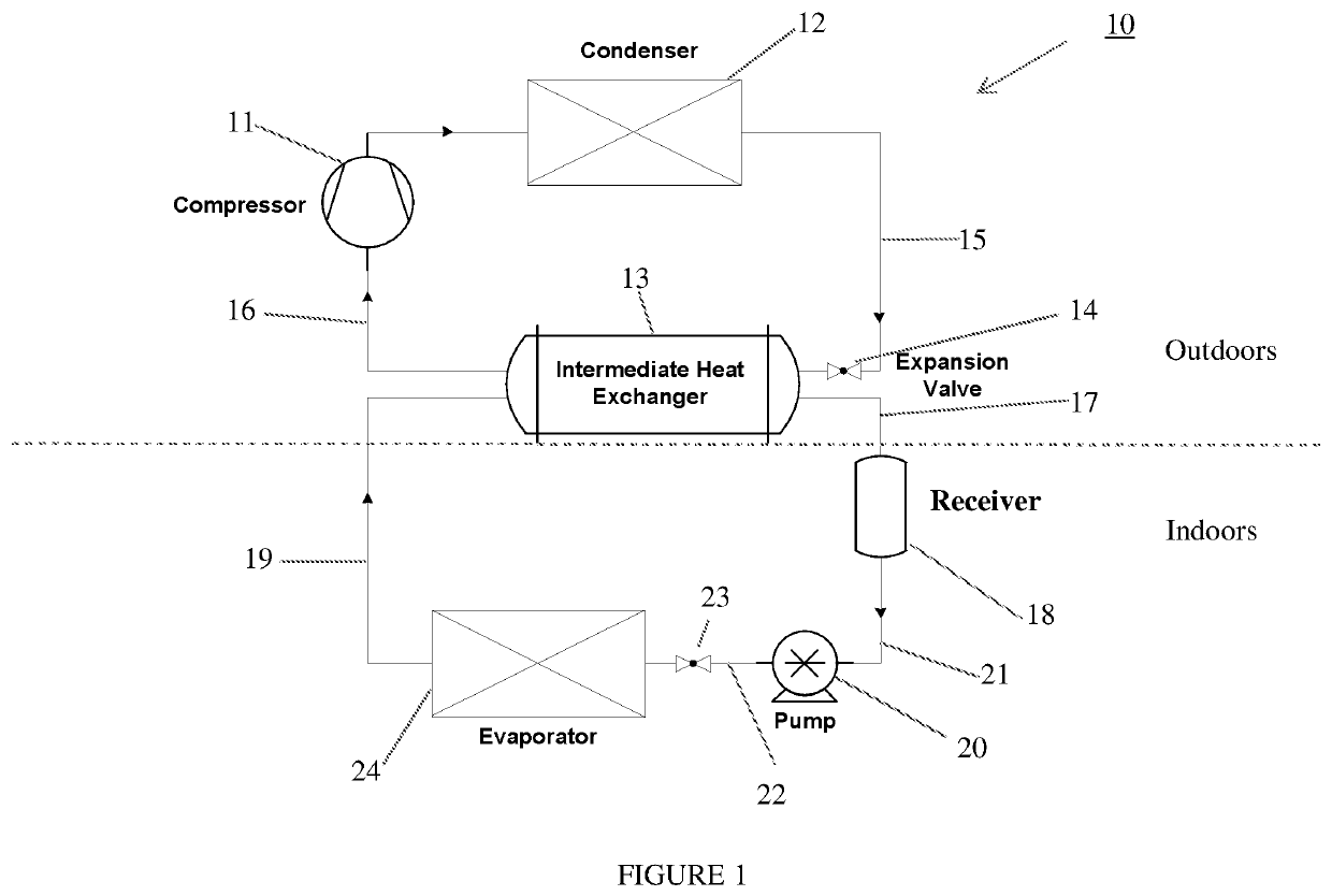
Example 1A (FIG. 1) Operating Conditions

[0066]A system configured as illustrated herein in FIG. 1 is operated according to the following operating parameters using a series of different first (outdoor) and second (indoor) refrigerants:

[0067]1. Condensing temperature=45° C., corresponding outdoor ambient temperature=35° C.

[0068]2. Condensing Temperature—Ambient Temperature=10° C.

[0069]3. Expansion device sub-cooling=5.0° C.

[0070]4. Evaporating temperature=7° C., corresponding indoor room temperature=27° C.

[0071]5. Evaporator Superheat=0.0° C. (flooded)

[0072]6. Intermediate Heat Exchanger Superheat=5.0° C.

[0073]7. Isentropic Efficiency=72%

[0074]8. Volumetric Efficiency=100%

[0075]9. Difference of saturation temperatures intermediate heat exchanger=5° C.

The results are provided (with percentages for blends shown in weight %) in Table 1A below:

[0076]

TABLE 1ASecondFirst (Outdoor)(Indoor)GWPGWPCa-RefrigerantRefrigerantPrimarySecondarypacityEfficiencyR410ANA1924100%100%PropaneR1233zd31100%9...

example 2a

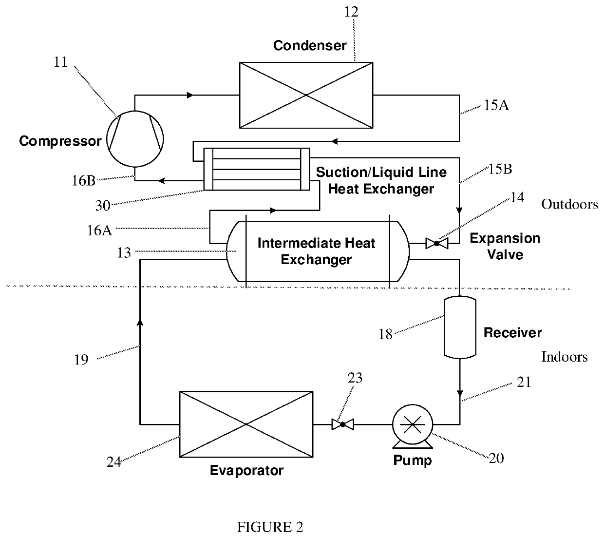
Example 2A (FIG. 2) Operating Conditions

[0084]A system configured as illustrated herein in FIG. 2 is operated according to the following operating parameters using a series of different first (outdoor) and second (indoor) refrigerants:

[0085]1. Condensing temperature=45° C., corresponding outdoor ambient temperature=35° C.

[0086]2. Condensing Temperature—Ambient Temperature=10° C.

[0087]3. Expansion device sub-cooling=5.0° C.

[0088]4. Evaporating temperature=7° C., corresponding indoor room temperature=27° C.

[0089]5. Evaporator Superheat=0.0° C. (flooded)

[0090]6. Intermediate Heat Exchanger Superheat=5.0° C.

[0091]7. Isentropic Efficiency=72%

[0092]8. Volumetric Efficiency=100%

[0093]9. Difference of saturation temperatures intermediate heat exchanger=5° C.

The results are provided (with percentages for blends shown in weight %) in Table 2A below:

[0094]

TABLE 2APrimarySecondaryGWPGWPEfficiency@Efficiency@Efficiency@Efficiency@Efficiency@RefrigerantRefrigerantPrimarySecondary0% effect.35% eff...

example 2b

Example 2B (FIG. 2)—Alteration of Condenser Temperature

[0095]A system configured as illustrated herein in FIG. 2 is operated according to the same operating parameters as Example 2A using a series of different first (outdoor) and second (indoor) refrigerants, except that the condensing temperature is adjusted for each blend in order to obtain an efficiency that substantially matches the efficiency achieved according to Comparative Example 1. The results are provided in Table 2B below:

[0096]

TABLE 2BTcond (° C.)Tcond (° C.)Tcond (° C.)Tcond (° C.)Tcond (° C.)PrimarySecondaryGWPGWP@ 0%@ 35%@ 55%@ 75%@ 85%RefrigerantRefrigerantPrimarySecondaryeffect.effect.effect.effect.effect.R410A192445.045.045.045.045.0PropaneR1233zd3141.741.942.142.342.4R1234yfR1233zd1141.241.842.242.642.8R1234zeR1233zd1142.242.743.043.343.5R32 / R1234yfR1233zd69141.141.641.942.342.5(10.0% / 90.0%)R32 / R1234zeR1233zd69142.142.542.843.143.3(10.0% / 90.0%)R32 / R1234yfR1233zd150141.041.241.441.641.7(22.0% / 79.0%)R32 / R1234zeR123...


PUM


Abstract

Refrigerant systems for conditioning air and / or items located within a dwelling including a high temperature refrigerant circulation loop located substantially outside of the dwelling and a low temperature transfer circuit, which contains HCFO-1233zd(E) substantially inside of the dwelling and at least one intermediate heat exchanger which permits exchange of heat between the high temperature circuit and the HFCO-1233zd(E) in the low temperature heat transfer circuit.

Description

CROSS-REFERENCE TO RELATED APPLICATIONS[0001]The present application claims priority to U.S. Provisional Application No. 62 / 295,731, filed Feb. 16, 2016, and is a continuation-in-part of U.S. application Ser. No. 15 / 400,891, filed Jan. 6, 2017 which application claims priority to U.S. Provisional Application No. 62 / 275,382, filed Jan. 6, 2016 the entire contents of which is hereby incorporated by reference.FIELD OF THE INVENTION[0002]The present invention relates to high efficiency, low-global warming potential (“low GWP”) air conditioning and related refrigeration systems and methods that are safe and effective.BACKGROUND[0003]In a typical air conditioning and refrigerant systems, a compressor is used to compress a heat transfer vapor from a lower to a higher pressure, which in turn adds heat to the vapor. This added heat is typically rejected in a heat exchanger, commonly referred to as a condenser. In the condenser the vapor, at least in major proportion, is condensed to produce ...

Claims


Application Information

Patent Timeline
Patent Type & Authority Patents(United States)
IPC IPC(8): F25B7/00F25B13/00F25B41/00F25B41/04
CPCF25B7/00F25B13/00F25B41/003F25B41/043F25B2313/0292F25B2500/222F25B2400/23F25B2313/02742F25B40/00F25B2400/13F25B2400/121F25B41/39
Inventor SETHI, ANKITYANA MOTTA, SAMUEL F.VERA BECERRA, ELIZABET DEL CARMEN
Owner HONEYWELL INT INC
Features
  • R&D
  • Intellectual Property
  • Life Sciences
  • Materials
  • Tech Scout
  • Unparalleled Data Quality
  • Higher Quality Content
  • 60% Fewer Hallucinations
Learn More