
Digital clock generation with randomized division of a source clock

a digital clock and source clock technology, applied in pulse generation with predetermined statistical distribution, pulse automatic control, pulse technique, etc., can solve the problems of fifo overflow/underflow, generated digital clocks with poor attenuation of low frequency spurs

Active Publication Date: 2021-02-02
TEXAS INSTR INC
View PDF7 Cites 1 Cited by
  • Summary
  • Abstract
  • Description
  • Claims
  • Application Information

AI Technical Summary

Benefits of technology

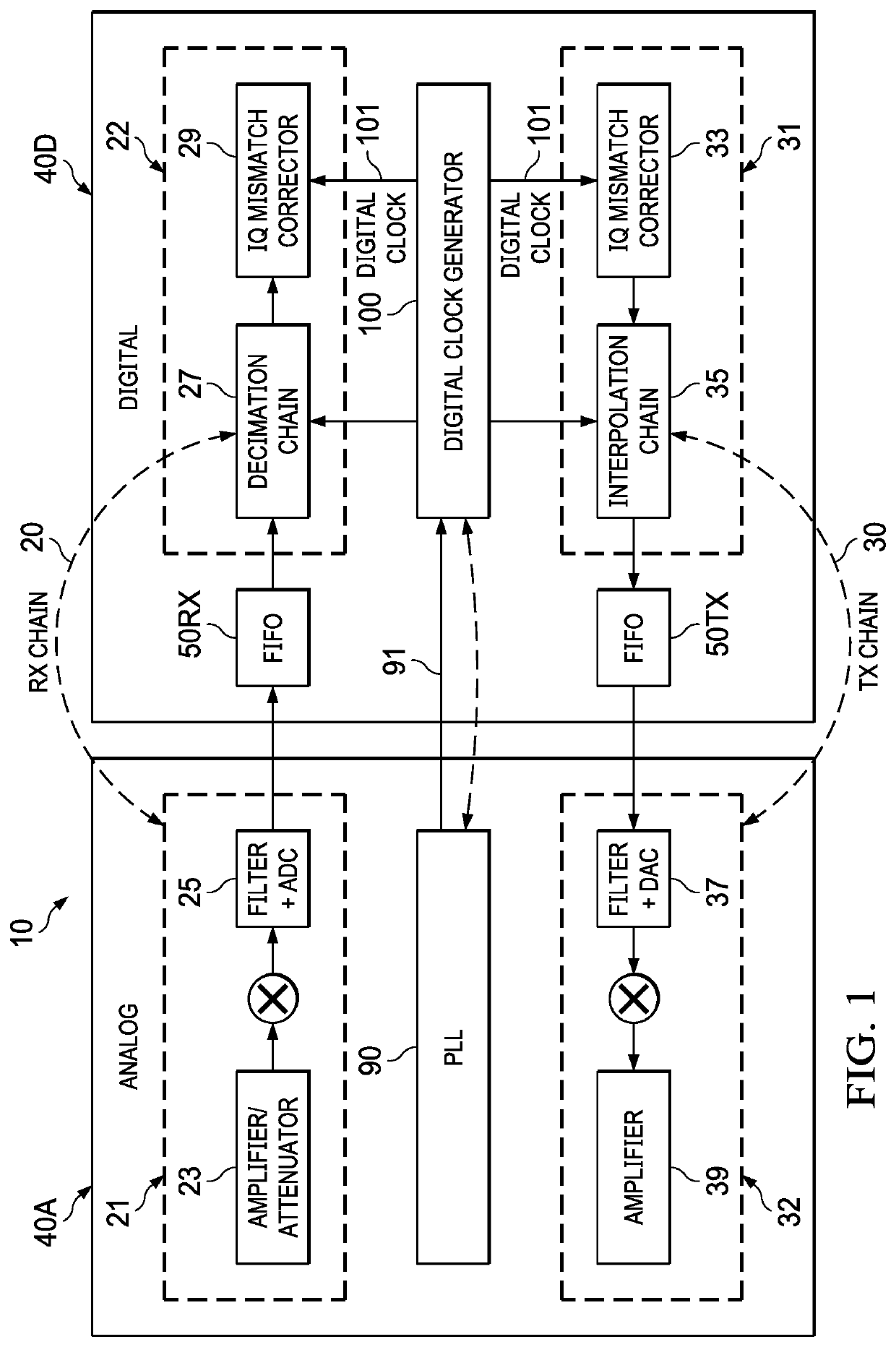
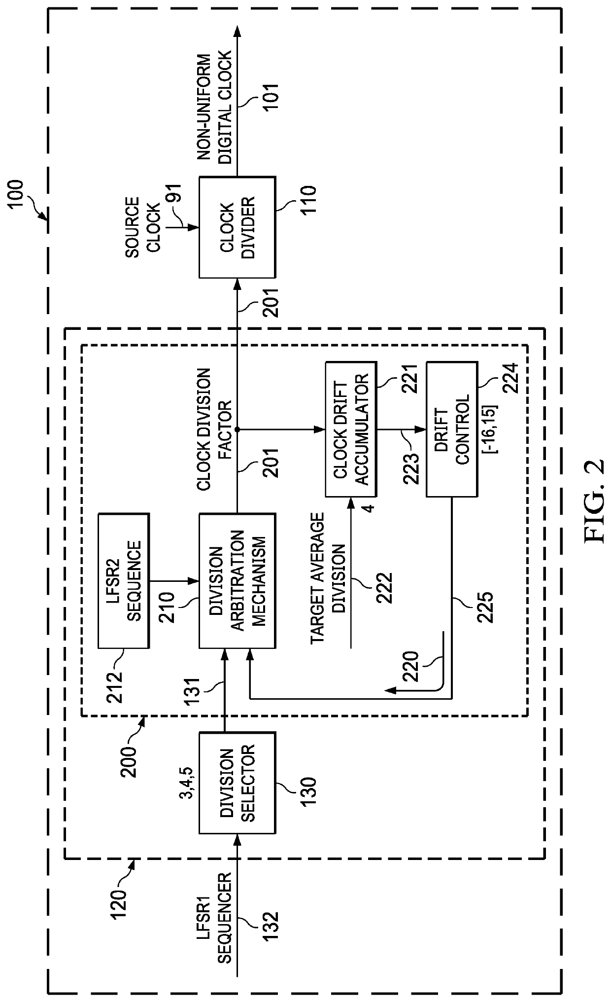
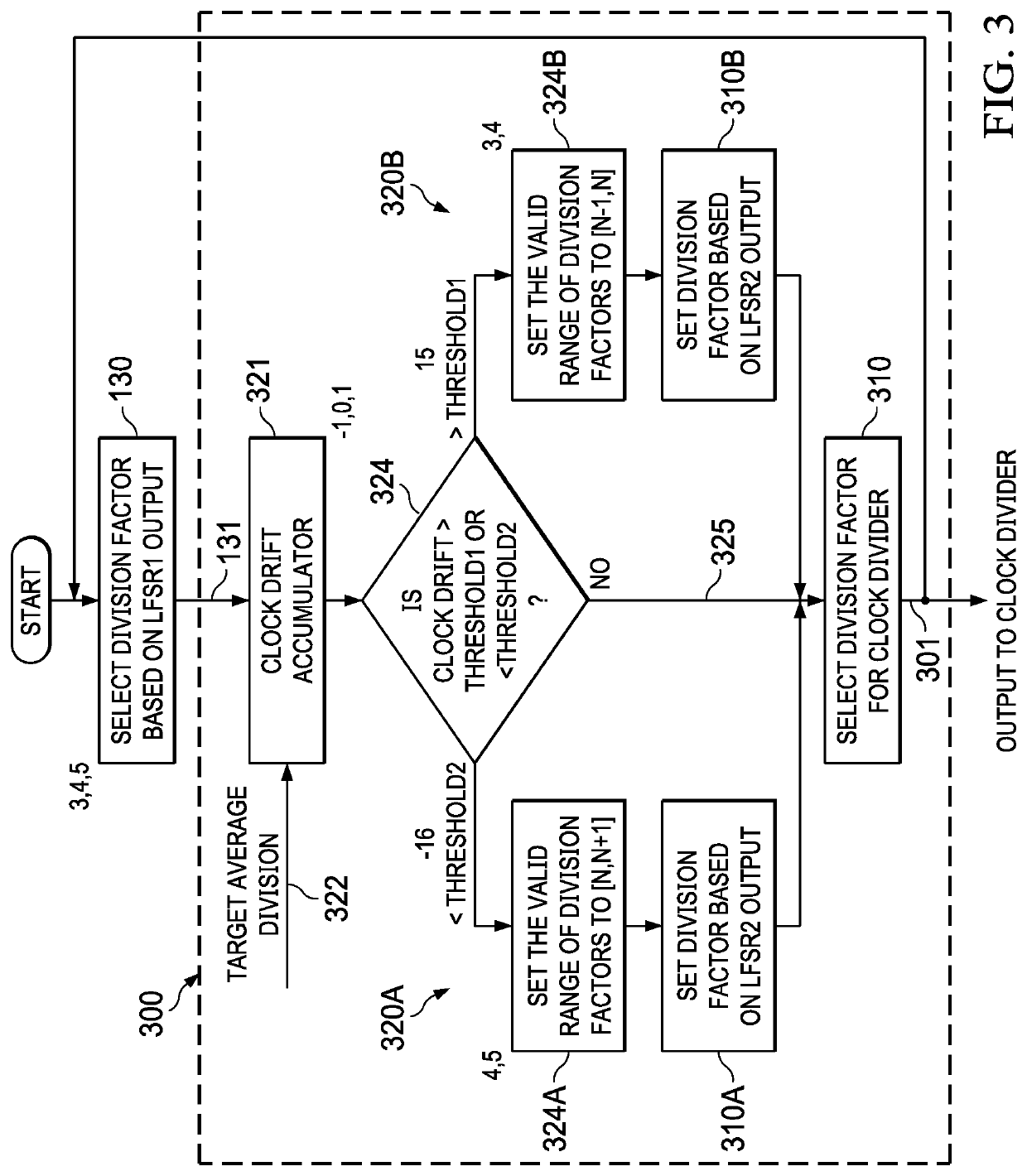
The patent describes a method and apparatus for generating a digital clock in a digital clock domain that is interfaced to another clock domain through a FIFO component. The method involves randomized division of a source clock based on a drift-corrected randomizing sequence of clock division factors, which helps to bound clock drift based on the depth of the FIFO. The apparatus includes a division selector circuitry and a division arbitration circuitry to generate the drift-corrected randomizing sequence of clock division factors. The technical effect of this invention is to improve the accuracy and stability of clock generation in a digital clock domain.

Problems solved by technology

However, accumulated drift of the randomized low frequency clock (relative to a uniform clock) becomes unbounded, causing FIFO overflow / underflow.
However, the generated digital clock has poor attenuation of the low frequency spurs which can couple to the analog.

Method used


Image

  • Digital clock generation with randomized division of a source clock
  • Digital clock generation with randomized division of a source clock
  • Digital clock generation with randomized division of a source clock

Examples


Embodiment Construction

[0024]This Description and the Drawings constitute a Disclosure, including design examples and implementations, and including illustrating various technical features and advantages for: digital clock generation for a digital clock domain receiving data through a FIFO interface, with randomized division (integer or fractional) of a source clock based on a drift-corrected randomizing sequence of clock division factors, so that clock drift is bounded based on a selected FIFO depth.

[0025]An example application is RF TX and / or RX analog / digital signal chains (such as an RF TX / RX transceiver), with a FIFO A / D interface for data transfers to / from the digital signal chain (clock domain). In other applications, the digital clock domain can be interfaced (through the FIFO) to another digital clock domain.

[0026]As used in this Disclosure, (a) randomized clock division means non-uniform clock division based on a randomizing sequence of random or pseudorandom division factors, such as generated ...


PUM


Abstract

A digital clock generator for a digital clock domain interfaced to another clock domain through a FIFO, includes division selector circuitry to provide an input randomizing sequence of clock division factors, selected from a defined set of clock division factors corresponding to a target average clock division, and division arbitration circuitry to generate a drift-corrected randomizing sequence of clock division factors, based at least in part on the input randomizing sequence of clock division factors, and an accumulated drift correction signal. A clock drift control loop generates the accumulated drift correction signal, based at least in part on an accumulated clock drift relative to the target average clock division. Clock generation can be based on randomized division with the drift-corrected randomizing sequence of clock division factors. The drift-corrected randomizing sequence of clock division factors can be generated so that clock drift is bounded based on a FIFO depth.

Description

CROSS-REFERENCE TO RELATED APPLICATIONS[0001]Priority is claimed under 37 CFR 1.78 and 35 USC 119(e) to INDIA Provisional Application 201841042423, filed 2018 Nov. 12, which is incorporated by reference in its entirety.BACKGROUND[0002]In mixed signal systems with analog and digital clock domains, to achieve optimal area and power, the digital logic can be designed to operate at a significantly lower frequency than the analog circuitry. For example, in an RF TX or RX (or transceiver TX / RX), where the analog TX or RX commonly operate in the GHz range, the digital logic can be designed to operate in the range of hundreds of MHz, such as for interpolation / decimation, digital pre-distortion (DPD), quadrature (IQ) mismatch compensation (or other correction of analog impairments).[0003]Digital clock spurs coupling to the analog modules can significantly impact the ability to meet operational / performance specifications. Digital clock spur coupling can be mitigated by frequency planning in t...

Claims


Application Information

Patent Timeline
Patent Type & Authority Patents(United States)
IPC IPC(8): H03L7/18H04B1/40H03K3/84
CPCH03L7/18H03K3/84H04B1/40H03K21/08
Inventor GUNTURI, SARMA SUNDARESWARATANGUDU, JAWAHARLALRANGACHARI, SUNDARRAJAN
Owner TEXAS INSTR INC
Learn More