Supercharge Your Innovation With Domain-Expert AI Agents!

Method for producing a rotor of a flow engine

a technology of flow engine and rotor, which is applied in the direction of machines/engines, mechanical equipment, liquid fuel engines, etc., can solve the problems of requiring replacement of damaged assemblies, high welding cost, and inability to produce integrally bladed rotors with outer shrouds

Active Publication Date: 2021-02-09
MAN ENERGY SOLUTIONS SA
View PDF12 Cites 0 Cited by
  • Summary
  • Abstract
  • Description
  • Claims
  • Application Information

AI Technical Summary

Benefits of technology

This approach allows for the production of aerodynamically and thermodynamically optimized, lightweight integrally bladed rotors with integral outer shrouds without the risks and costs associated with welding, offering enhanced reliability and efficiency.

Problems solved by technology

Producing an integrally bladed rotor with outer shroud by welding is expensive and error-prone.
During the welding, there is the risk that the assemblies to be welded to one another are damaged.
Because of this, it may be required to replace damaged assemblies.

Method used


Image

  • Method for producing a rotor of a flow engine

Examples


Embodiment Construction

[0014]The present invention relates to a method for producing a rotor of a turbo machine, in particular of a compressor or alternatively of a turbine.

[0015]The method produces an integrally bladed rotor with integral outer shroud, in the case of which moving blades of the rotor are thus an integral part of a radially inner rotor basic body, and wherein the rotor furthermore comprises an outer shroud radially outside which is connected to the moving blades in a fixed manner radially outside.

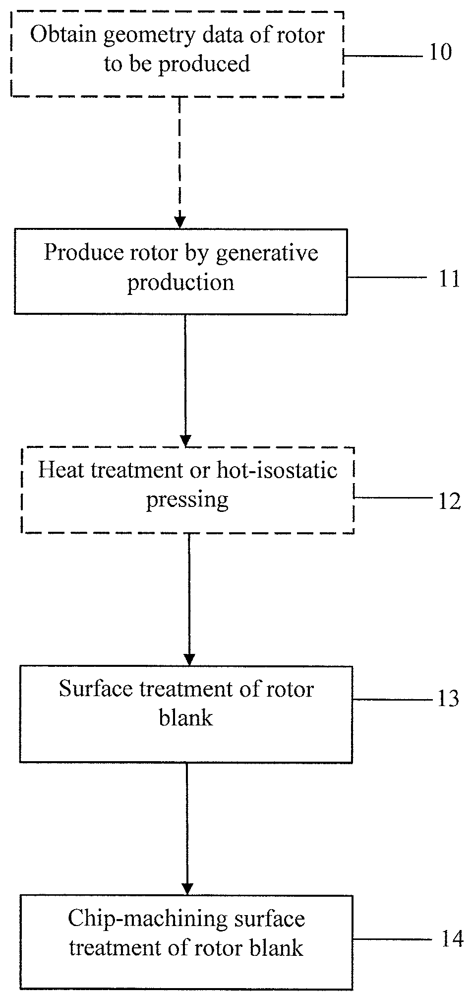
[0016]In the present invention, a rotor blank is initially produced by a generative production method, comprising integral moving blades and the integral outer shroud. Accordingly, the moving blades are an integral part of a rotor basic body, while the outer shroud is likewise an integral part of the rotor blank. Following this step, the rotor blank is subjected, on flow-conducting sections, to an abrasive cutting surface treatment, and, separately thereof, to a chip-machining surface treatment on...


PUM

PropertyMeasurementUnit
weightaaaaaaaaaa
structuresaaaaaaaaaa

Abstract

The invention relates to a method for producing a rotor of a flow engine, namely an integrally bladed rotor with an integral outer shroud, comprising at least the following steps: a rotor blank comprising the integral rotor blades and the integral outer shroud is first produced by means of a generative production method; the rotor blank is then subjected to a separating surface treatment at flow-guiding sections and is subjected, separately therefrom, to a machining surface treatment at non-flow-guiding sections.

Description

RELATED APPLICATIONS[0001]This is a U.S. National Phase under 35 U.S.C. § 371 of International Application No. PCT / EP2016 / 059982, filed on May 4, 2016, and claims the priority of German Patent Application No. 10 2015 006 463.0, filed on May 20, 2015, the entire contents of which are hereby incorporated by reference.BACKGROUND OF THE INVENTION1. Field of the Invention[0002]The invention relates to a method for producing a rotor of a turbo machine.2. Description of the Related Art[0003]A turbo machine, which can be designed as compressor or as turbine, comprises stator-side assemblies and rotor-side assemblies. The rotor-side assemblies include a rotor carrying so-called moving blades. Particularly preferably, integrally bladed rotors are employed in turbo machines, in the case of which the moving blades are an integral part of a rotor basic body. Furthermore, rotors, which comprise an outer shroud radially on the outside, are known from the prior art.[0004]German Patent Publication N...

Claims


Application Information

Patent Timeline
Patent Type & Authority Patents(United States)
IPC IPC(8): B22F3/105B22F3/24C22C1/04F04D29/02F04D29/28F01D5/02F01D5/06
CPCB22F3/1055B22F3/24C22C1/0458F01D5/02F01D5/06F04D29/023F04D29/284B22F2998/10F05D2230/10F05D2230/11F05D2230/13F05D2230/18F05D2230/22F05D2230/31F05D2230/42F05D2240/20Y02P10/25B22F3/15B22F10/00B22F10/66B22F10/28B22F10/64B22F2003/247B22F2003/248B23P15/006B22F2999/00B33Y80/00B33Y40/20B33Y10/00
Inventor THON, RALF
Owner MAN ENERGY SOLUTIONS SA
Features
  • R&D
  • Intellectual Property
  • Life Sciences
  • Materials
  • Tech Scout
  • Unparalleled Data Quality
  • Higher Quality Content
  • 60% Fewer Hallucinations
Learn More