System, motor controller and associated method

a technology of motor controller and controller, applied in the field of electric motors, can solve the problems of inconvenient installation and high manufacturing cost of wiring harnesses needed to transmit the command signal from the user interface to the motor

Active Publication Date: 2021-02-09
REGAL BELOIT AMERICA
View PDF32 Cites 0 Cited by
  • Summary
  • Abstract
  • Description
  • Claims
  • Application Information

AI Technical Summary

Benefits of technology

The patent text is about a system that uses multiple speed motors to improve performance and save energy. However, the current wiring harnesses for transmitting command signals from user interfaces to the motors are expensive and difficult to install. The patent proposes a solution using a timer and processor to operate the motors to achieve a minimum number of daily air changes. The technical effects are improved performance and energy savings with a simpler and more cost-effective installation process.

Problems solved by technology

The wiring harnesses needed to transmit the command signal from the user interface to the motor are expensive to manufacture and inconvenient to install, particularly in existing structures.

Method used


Image

  • System, motor controller and associated method
  • System, motor controller and associated method
  • System, motor controller and associated method

Examples


Embodiment Construction

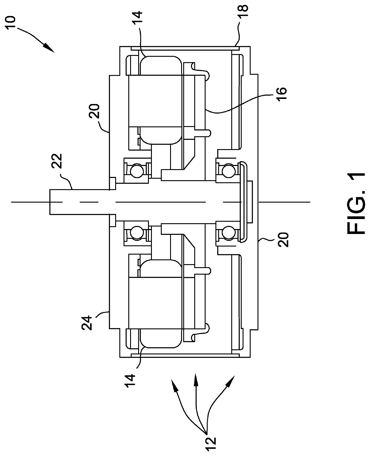
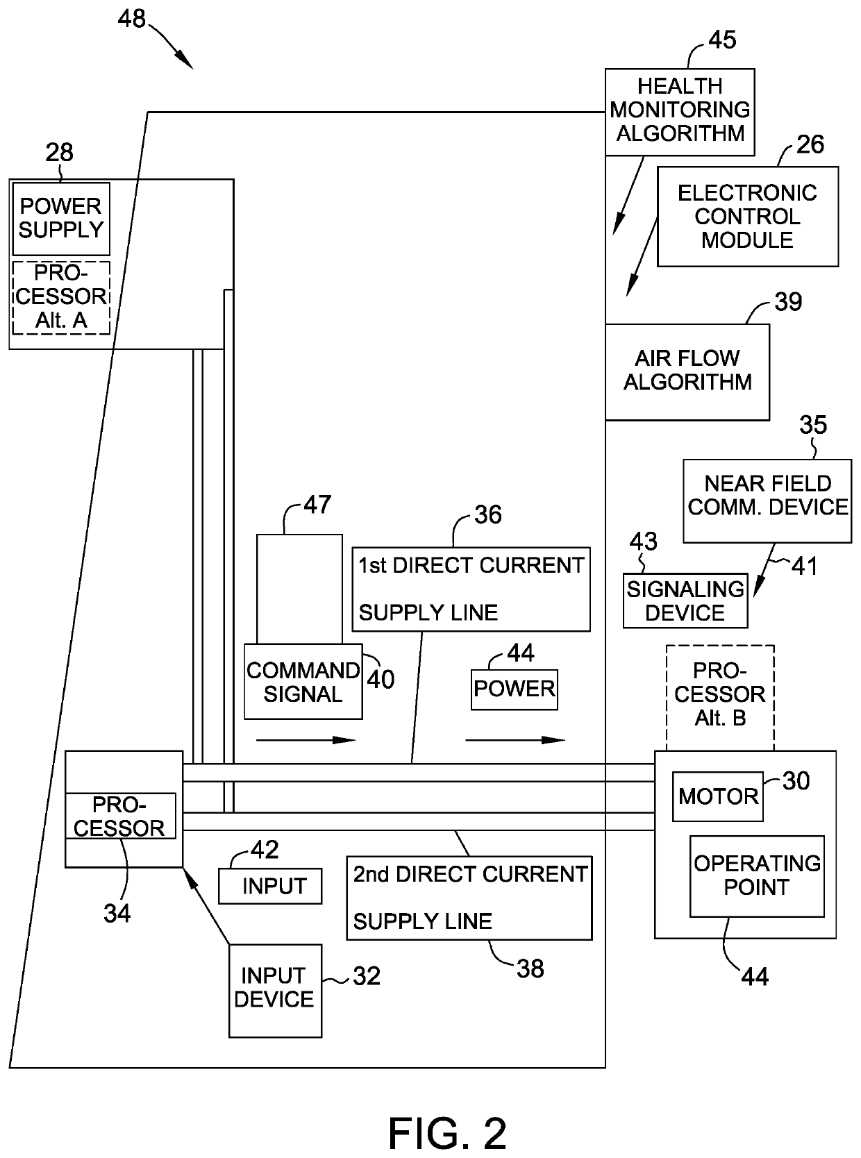
[0083]The method, systems and apparatus described herein facilitate the transmission of command signals to an electric machine.

[0084]The electric machine typically includes a housing for containing and supporting a stator that is excited by an electrical source that excites an electromagnetic field in coils in the stator. The coils interact with a rotor rotatably supported in the housing to provide the mechanical rotational energy for the electrical machine.

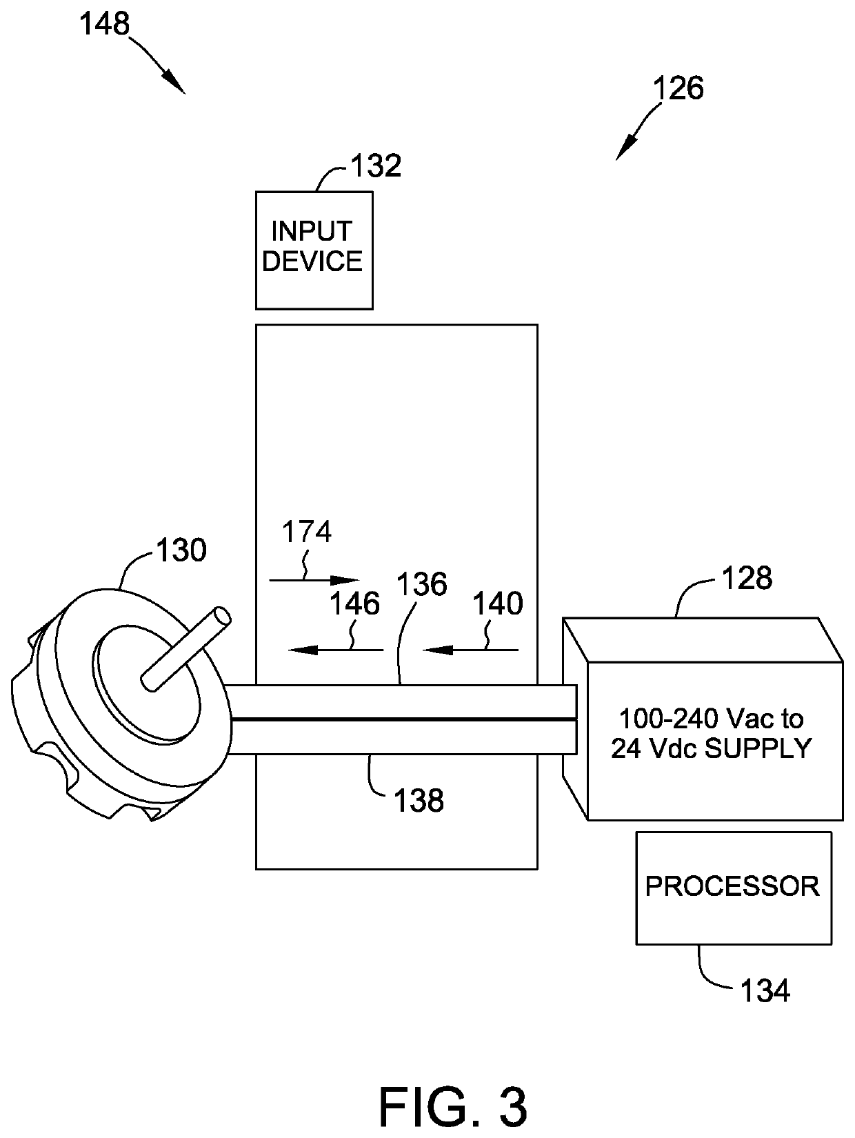
[0085]Electric machines or motors are utilized in many varied application and are energized utilizing a user interface. The motors may be positioned in locations not easily accessible to the user. Such applications include ceiling fans, HVAC applications and refrigeration applications. In order to provide convenient access to the user interface, such applications have a user interface spaced a significant distance from the motor.

[0086]To provide improved performance and energy savings multiple speed motors are frequently used. Th...


PUM


Abstract

An electronic control module is provided. The electronic control module is operably connected to a power supply for providing power to a motor. The electronic control module includes an input device, a processor coupled to the input device, and first and second current supply lines. The processor is configured to generate a command signal in response to an input supplied by the input device and transmit the command signal to the motor. The command signal controls an operating point of the motor. The first and second current supply lines are operably connectable to the motor and the processor. At least one of the current supply lines, the input device and the processor are adapted to utilize the current supply lines both to transmit power to the motor and to transmit the command signal to the motor over the current supply lines.

Description

BACKGROUND OF THE INVENTION[0001]The embodiments described herein relate generally to an electric machine, and more specifically, to an electric motor.[0002]An electric machine is typically in the form of an electric generator or an electric motor. The machine typically has a centrally located shaft that rotates relative to the machine. Electrical energy applied to coils within the machine initiates the relative motion that transfers the power to the shaft and, alternatively, mechanical energy from the relative motion of the generator excites electrical energy into the coils. For expediency, the machine will be described hereinafter as a motor. It should be appreciated that a machine may operate as a generator and vice versa.[0003]A stationary assembly, also referred to as a stator, includes a stator core and coils or windings positioned around portions of the stator core. It is these coils to which energy is applied to initiate this relative motion which transfers the power to a ro...

Claims


Application Information

Patent Timeline
Patent Type & Authority Patents(United States)
IPC IPC(8): F24F11/46H04B3/54H02P5/74H04W4/80F24F11/64F24F11/88F24F11/65F24F11/58G05B19/042H02P23/00F24F11/77
CPCF24F11/46F24F11/58F24F11/64F24F11/65F24F11/88G05B19/042H02P5/74H02P23/0077H04B3/548H04W4/80F24F11/77G05B2219/2614Y02B30/70
Inventor MULLIN, PAUL STEVENSMITH, MICHAEL DAVIDHAMILTON, KATIE DA-NELLEKUTCHERLAPATI, SRINIVAS CHANDU
Owner REGAL BELOIT AMERICA
Why Eureka
Try Eureka