Method and system for 4D radiological intervention guidance (4D-cath)

a radiological intervention and guidance technology, applied in the field of imaging methods for radiologically guided instruments, can solve the problems of mr imaging still requiring special arrangements, interventionists with a high degree of uncertainty regarding the position of instruments and current surroundings, and radiologically guided interventions are currently limited by known imaging methods, etc., to avoid excessive radiation dose for patients, improve radiological guided interventions, and avoid the effect of excessive radiation dos

Active Publication Date: 2021-02-16
DEUTES KREBSFORSCHUNGSZENT STIFTUNG DES OFFENTLICHEN RECHTS +2
View PDF8 Cites 0 Cited by
  • Summary
  • Abstract
  • Description
  • Claims
  • Application Information

AI Technical Summary

Benefits of technology

[0010]The present invention aims to provide a method for true 4D imaging which overcomes above mentioned limitations to improve radiological guided interventions. It is a further object of the present invention to provide a method for fully CT guided medical intervention providing three-dimensional information in real time during the intervention. The present invention particularly aims at providing 4D CT imaging that avoids excessive radiation dose for the patient and can be routinely used in medical applications.

Problems solved by technology

Radiologically guided interventions are currently limited by known imaging methods, because known imaging methods do not allow 4D imaging (3 spatial dimensions plus time), while radiological interventions are a 4D process.
Both methods leave the interventionist with a high degree of uncertainty regarding the position of his instruments and the current surroundings.
Nevertheless, MR imaging still requires special arrangements to detect and visualize the instruments used for interventions.
In this respect CT is due to the nature of X-Rays easier to handle, but present CT techniques such as CT-fluoroscopy require excessive radiation doses, preventing them from being routinely used.

Method used


Image

  • Method and system for 4D radiological intervention guidance (4D-cath)
  • Method and system for 4D radiological intervention guidance (4D-cath)
  • Method and system for 4D radiological intervention guidance (4D-cath)

Examples


Embodiment Construction

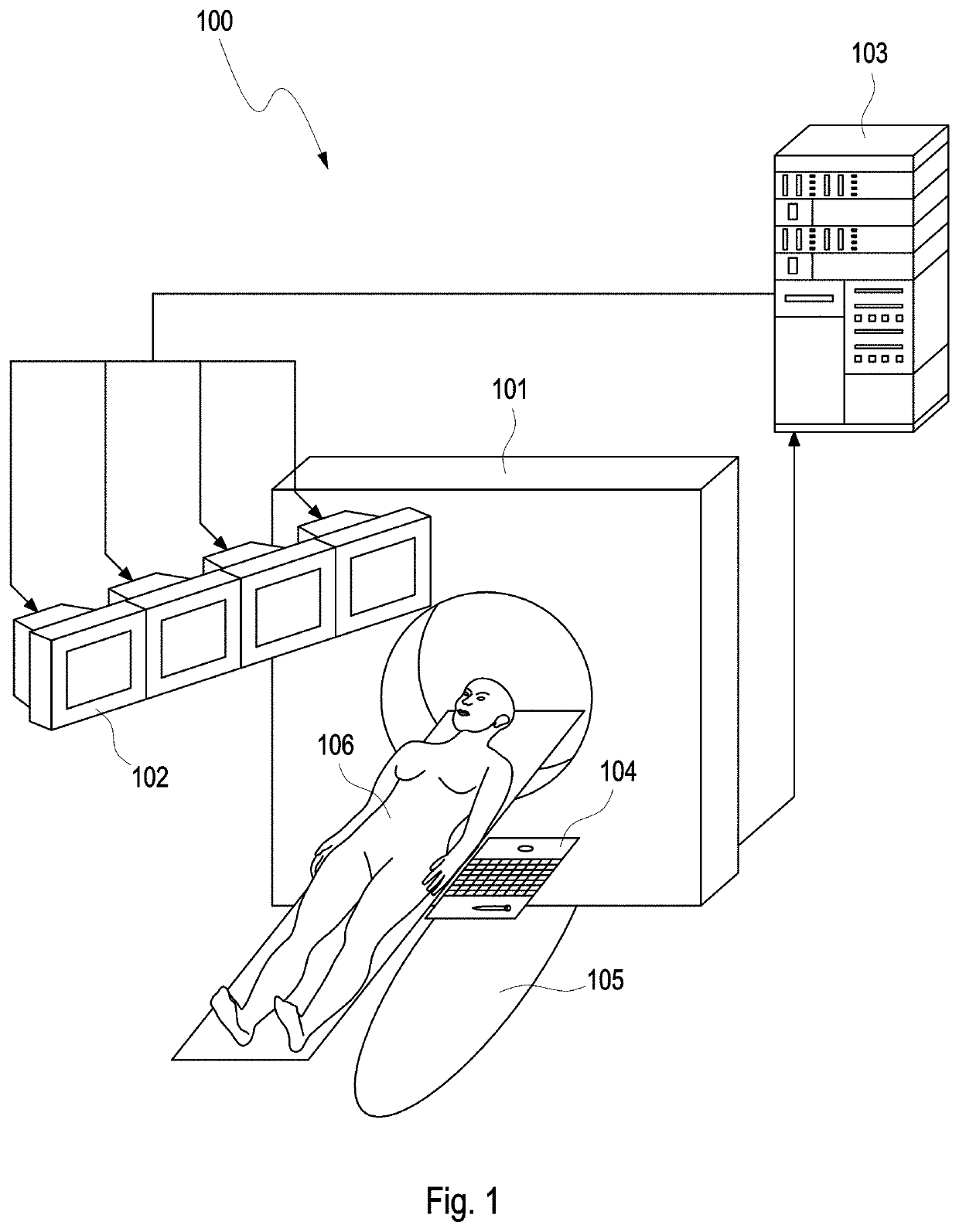
>[0070]FIG. 1 shows an exemplary configuration of the 4D-CATH lab including a CT scanner 101 in communication with a high performance computing device (HPC) 103 further in communication with one display or an array of displays 102 to provide the operator 105 with imaging information for guiding the intervention. The tomography system 101 is directly connected to the HPC 103 like conventional clusters, GPU-systems, GPU-clusters, cloud systems or other mainframes, where the actual reconstruction of images is performed. Thus, the HCP 103 receives projections measured by the CT scanner 101 and sends reconstructed, updated images to at least one of the displays of the array of displays 102.

[0071]In an exemplary embodiment, the CT scanner 101 comprises a continuously rotating, gantry-based CT scanner 101 with a flat-panel detector. Such a system is for instance described in R. Gupta et al. (Flat-panel volume CT: fundamental principles, technology, and applications. Radiographics. 2008; 28...


PUM


Abstract

An imaging method for radiologically guiding an instrument during medical interventions on an object is disclosed. First, a prior volumetric image of the object is provided, followed by periodically providing a current volumetric image on-the-fly during the intervention to an operator by measuring an undersampled set of projections of the object and reconstructing the current image based on changes between the prior volumetric image or an updated prior image and the undersampled set of projections. The method and corresponding system are used for radiologically guiding medical interventions on an object. The system includes a first image provider, an imaging apparatus for measuring undersampled sets of projections, and a processor. The processor communicates with the imaging apparatus for providing updated images on-the-fly during the intervention by reconstructing the updated image based on changes between the first image or an update of the first image and the undersampled sets of projections.

Description

[0001]This application is a national stage application of PCT / EP2011 / 073091 filed Dec. 16, 2011, which claims priority to U.S. Provisional Application No. 61 / 425,308, filed Dec. 21, 2010, the entire contents and disclosures of which are hereby incorporated by reference.FIELD OF INVENTION[0002]The present invention relates to an imaging method for radiologically guiding an instrument during medical interventions on an object. The invention further refers to a system for radiologically guiding medical interventions on an object.[0003]Radiologically guided interventions are currently limited by known imaging methods, because known imaging methods do not allow 4D imaging (3 spatial dimensions plus time), while radiological interventions are a 4D process. Current means of intervention guidance are either continuous projective imaging (X-ray fluoroscopy) or manipulate-and-shoot computed tomography (CT) imaging. Both methods leave the interventionist with a high degree of uncertainty regar...

Claims


Application Information

Patent Timeline
Patent Type & Authority Patents(United States)
IPC IPC(8): A61B5/06G06T11/00A61B1/267A61B5/00A61B5/055A61B6/03A61B6/00
CPCA61B5/062A61B1/2676A61B5/0042A61B5/0044A61B5/055A61B6/032A61B6/501A61B6/503G06T11/006A61B6/405A61B6/542G06T2211/412G06T2211/428G06T2211/436
Inventor KUNTZ, JANBARTLING, SOENKEKACHELRIESS, MARC
Owner DEUTES KREBSFORSCHUNGSZENT STIFTUNG DES OFFENTLICHEN RECHTS
Why Eureka
Try Eureka