
Mirror defogger

a defogger and mirror technology, applied in lighting and heating apparatus, heating types, instruments, etc., can solve the problems of inconvenient use, inconvenient use, and inability to use fogged mirrors for shaving,

Active Publication Date: 2021-02-16
WINTERVENTION LLC
View PDF41 Cites 0 Cited by
  • Summary
  • Abstract
  • Description
  • Claims
  • Application Information

AI Technical Summary

Benefits of technology

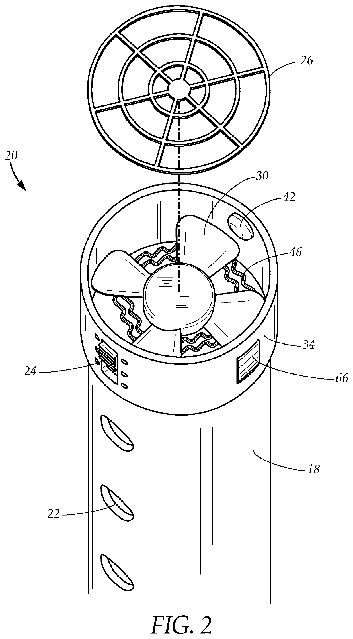
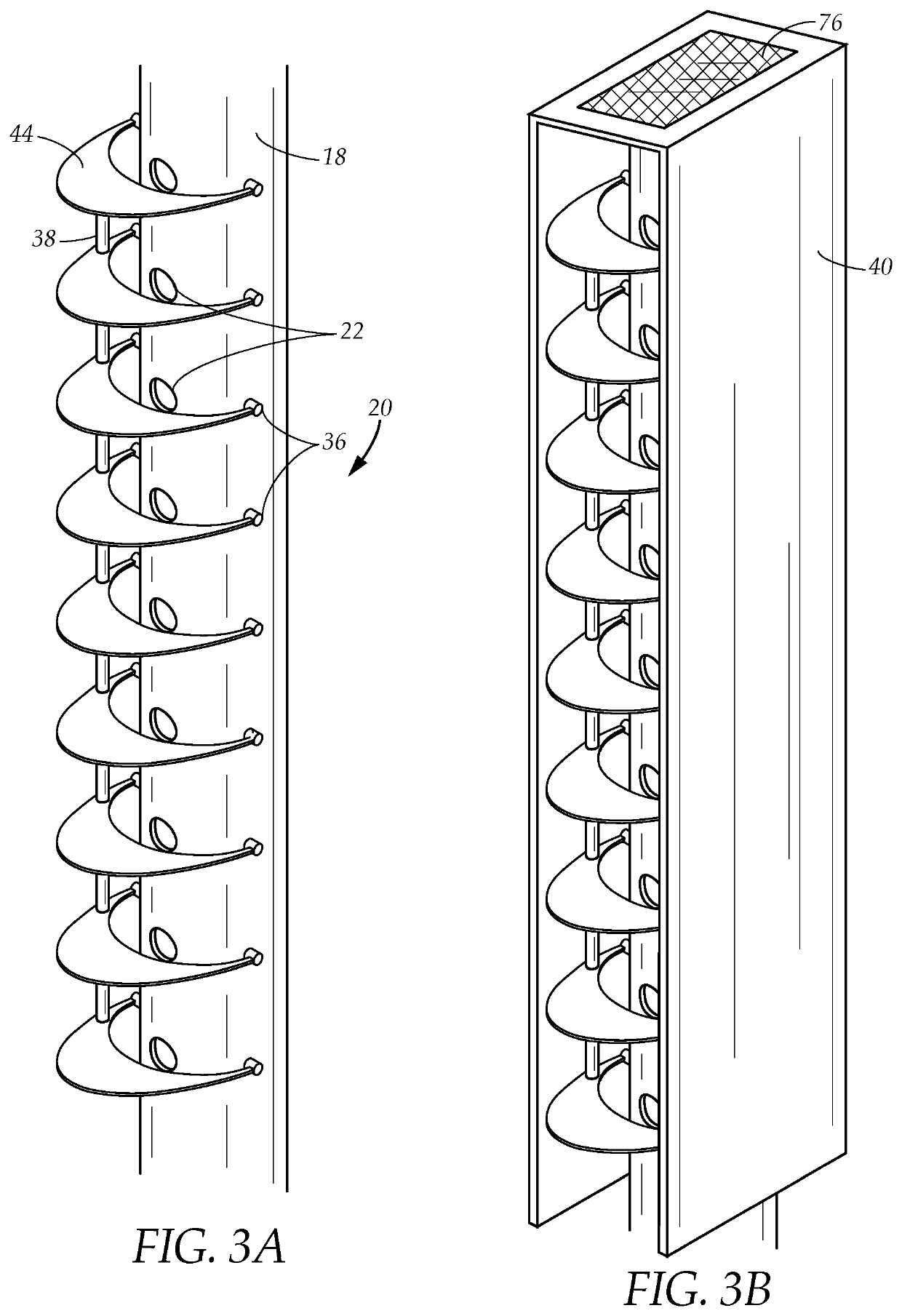
The present patent provides a system for defogging a mirror in a steamy bathroom. The system includes an impeller and a plurality of heating elements in a tube assembly for blowing hot air onto a fogged mirror. The system also has a plurality of mounting assemblies for all types of mirrors, including a portable mounting assembly with a rechargeable battery that selectively attaches on or adjacent to a mirror. The system has an articulated arm mounting assembly and a mounting assembly fixture. The technical effects of the present patent include providing an adaptable and portable system for defogging a mirror in a steamy bathroom, which can effectively and efficiently defog the mirror without causing any damage or discomfort to the user.

Problems solved by technology

Generally, the entire room becomes steamy and remains steamy for a period after the shower or bath.
Unfortunately, a fogged mirror is useless for shaving, applying makeup, styling hair and all those tasks that are required by a person to look presentable when preparing for the day's or evening's events.
Ceiling fans, exhaust fans and hair dryers are often employed with limited success.
The ceiling fans and exhaust fans clear the steam in general but do little to remove the fog on the mirror.
The hair dryer heats relatively small areas on the surface of the mirror and it is a slow, tedious process.
Often the mirror starts to fog over again before the user is finished removing the fog.
While these units may be suitable for the particular purpose employed, or for general use, they would not be as suitable for the purposes of the present disclosure as disclosed hereafter.

Method used


Image

  • Mirror defogger
  • Mirror defogger
  • Mirror defogger

Examples


Embodiment Construction

[0041]FIG. 7 illustrates an example embodiment of a mirror defogging system 10 configured for defogging a mirror 12 by eliminating condensate 14 from the mirror surface. In a typical bathroom as illustrated in FIG. 7, the mirror 12 hangs on a wall 16. However, it is understood that other configurations are possible, such as a free-standing mirror on a pedestal, a mirror attaching to the wall by an accordion mount or an articulated arm. As explained below, the mirror defogging system is configured to defog mirrors in various configurations and is not limited to a wall-mounted mirror 12.

[0042]The mirror defogging system 10 has a tube assembly 20 selectively coupling to a mounting assembly 40 described in detail hereinbelow. The mirror defogging system has a plurality of mounting assemblies adaptable for portability as well as various configurations of mirrors. The mounting assembly 40A in FIG. 7 is a first example embodiment of possible mounting assemblies. The mounting assembly 40A r...


PUM


Abstract

An adaptable system for defogging a mirror in a steamy bathroom having a tube assembly with a plurality of openings with an impeller and a plurality of heating elements for blowing hot air through the openings onto the fogged mirror. In one example embodiment, the tube assembly has louvers directing the hot air from the openings. The system has a plurality of mounting assemblies configured for all types of mirrors operative for coupling to the tube assembly, such as a portable mounting assembly with a rechargeable battery that selectively attaches on or adjacent to a mirror. The system has an articulated arm mounting assembly in one example embodiment. The system has a mounting assembly fixture in another example embodiment. A kit comprises the tube assembly and at least one mounting assembly.

Description

CROSS-REFERENCE TO RELATED APPLICATIONS[0001]This application is a continuation-in-part nonprovisional utility application of the non-provisional utility application Ser. No. 15 / 447,577 filed on Mar. 2, 2017 in the United State Patent and Trademark Office which is a continuation-in-part of the non-provisional utility application Ser. No. 14 / 688,021, filed in the United States Patent and Trademark Office on Apr. 16, 2015, now U.S. Pat. No. 9,612,035, and claims the priority thereof and is expressly incorporated herein by reference in its entirety.TECHNICAL FIELD[0002]The present disclosure relates generally to a mirror defogger. More particularly, the present disclosure relates to a mirror defogging system.BACKGROUND[0003]Bathroom mirrors fog, that is, become covered with condensed water vapor, when a nearby shower or bath is running. Generally, the entire room becomes steamy and remains steamy for a period after the shower or bath. The mirror is usually the last surface from which t...

Claims


Application Information

Patent Timeline
Patent Type & Authority Patents(United States)
IPC IPC(8): H05B1/02H05B3/84F24H3/00F24H9/00F24H3/04F24H9/06
CPCH05B3/845F24H3/002F24H3/0405F24H9/0057F24H9/0063F24H9/06F24D2220/04F24D2220/042H05B2203/022G02B27/0006
Inventor WINTERS, FRANK
Owner WINTERVENTION LLC
Learn More