Supercharge Your Innovation With Domain-Expert AI Agents!

Unitary body turbine shroud for turbine systems

a turbine system and unitary body technology, applied in the direction of engine fuction, leakage prevention, machines/engines, etc., can solve the problems of not allowing the shroud to be opened, the shroud may undergo undesirable thermal expansion, and damage to the shroud

Active Publication Date: 2021-02-23
GENERAL ELECTRIC CO
View PDF43 Cites 0 Cited by
  • Summary
  • Abstract
  • Description
  • Claims
  • Application Information

AI Technical Summary

Benefits of technology

The patent text describes a turbine system with a turbine shroud that is designed to improve performance. The turbine shroud includes a support portion, forward and aft hooks, an intermediate portion with a curved section, and a seal portion. The technical effect of this design is to improve the flow of hot gas through the turbine system, which leads to better performance and efficiency.

Problems solved by technology

Over time and / or during exposure, the turbine shrouds may undergo undesirable thermal expansion.
The thermal expansion of turbine shrouds may result in damage to the shrouds and / or may not allow the shrouds to maintain a seal within the turbine component for defining the fluid flow path for the operational fluid.
When the turbine shrouds become damaged or no longer form a satisfactory seal within the turbine component, the operational fluid may leak from the flow path, which in turn reduces the operational efficiency of the turbine component and the entire turbine system.
Each of these cooling processes create issues during operation of the turbine component.
For example, the cooling air utilized in film cooling may mix with the operational fluid flowing through the fluid flow path, and may cause turbulence within the turbine component.
However, the patterned surfaces are not usually conducive with film cooling processes for cooling the shroud.
As the number of pieces assembled to form the turbine shroud increases, so may the likelihood of possible uncoupling and / or damage to the turbine shroud and / or the turbine component.

Method used


Image

  • Unitary body turbine shroud for turbine systems
  • Unitary body turbine shroud for turbine systems
  • Unitary body turbine shroud for turbine systems

Examples


Embodiment Construction

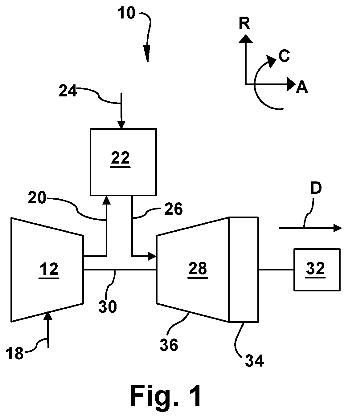
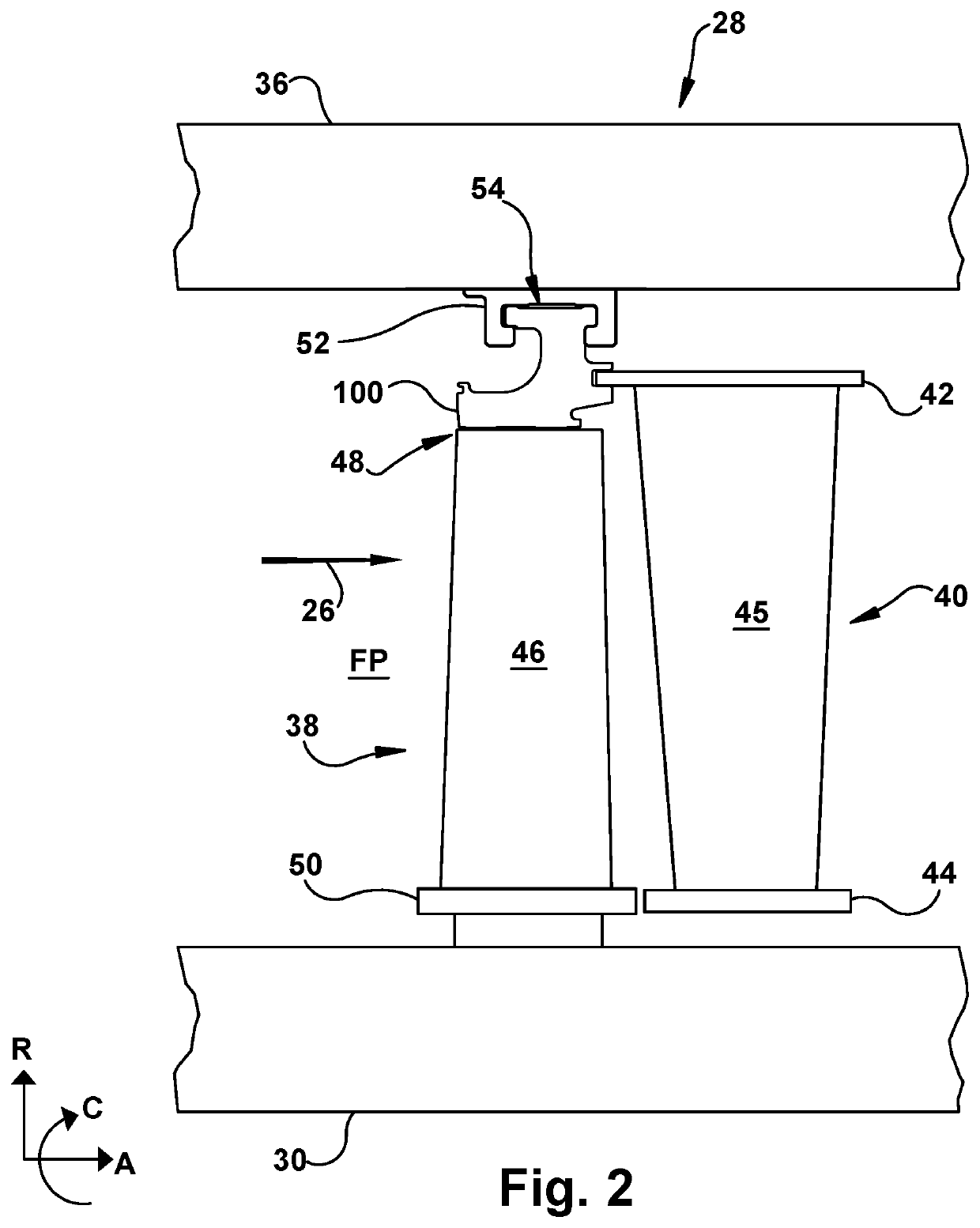
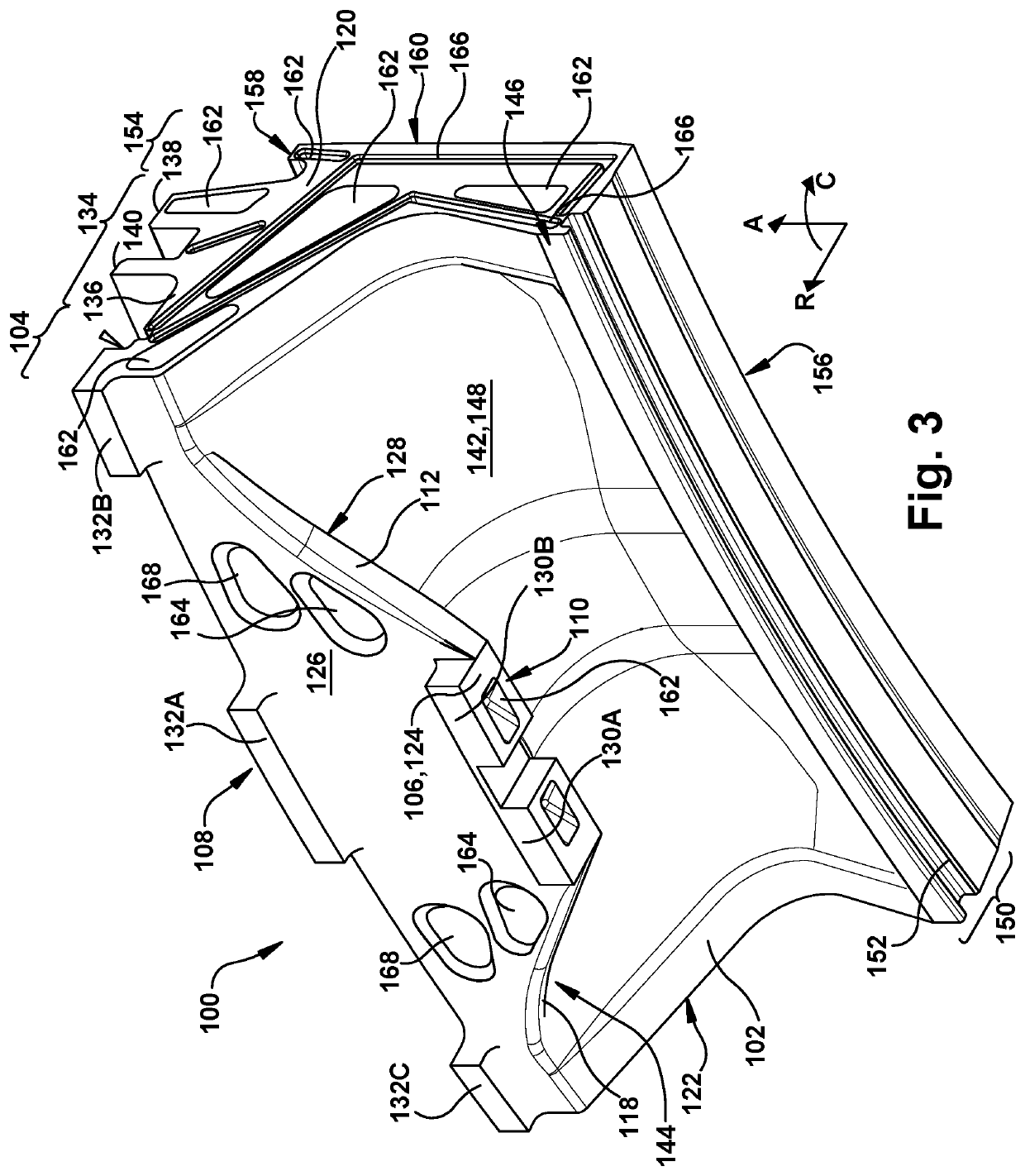
[0022]As an initial matter, in order to clearly describe the current disclosure it will become necessary to select certain terminology when referring to and describing relevant machine components within the scope of this disclosure. When doing this, if possible, common industry terminology will be used and employed in a manner consistent with its accepted meaning. Unless otherwise stated, such terminology should be given a broad interpretation consistent with the context of the present application and the scope of the appended claims. Those of ordinary skill in the art will appreciate that often a particular component may be referred to using several different or overlapping terms. What may be described herein as being a single part may include and be referenced in another context as consisting of multiple components. Alternatively, what may be described herein as including multiple components may be referred to elsewhere as a single part.

[0023]In addition, several descriptive terms...


PUM


Abstract

A turbine shroud for turbine systems may include a unitary body including a support portion coupled directly to a turbine casing of the turbine system, and forward hook(s) and aft hook(s) formed integral with the support portion. The unitary body may also include an intermediate portion formed integral with and extending from the support portion. The intermediate portion may include a non-linear segment extending from the support portion, and a forward segment formed integral with the non-linear segment. The forward segment of the intermediate portion may be positioned axially upstream of the forward hook(s). Additionally the unitary body may include a seal portion formed integral with the intermediate portion, opposite the support portion. The seal portion may include a forward end formed integral with the intermediate portion. The forward end may be positioned axially upstream of the forward hook(s).

Description

CROSS-REFERENCE TO RELATED APPLICATION[0001]This application is related to co-pending U.S. application Ser. Nos. 16 / 263,548 and 16 / 263,430, filed concurrently, currently pending, and are hereby incorporated by reference in their entirety.BACKGROUND OF THE INVENTION[0002]The disclosure relates generally to a turbine system component, and more particularly, to a unitary body turbine shroud for turbine systems.[0003]Conventional turbomachines, such as gas turbine systems, generate power for electric generators. In general, gas turbine systems generate power by passing a fluid (e.g., hot gas) through a turbine component of the gas turbine system. More specifically, inlet air may be drawn into a compressor to be compressed. Once compressed, the inlet air is mixed with fuel to form a combustion product, which may be reacted by a combustor of the gas turbine system to form the operational fluid (e.g., hot gas) of the gas turbine system. The fluid may then flow through a fluid flow path for...

Claims


Application Information

Patent Timeline
Patent Type & Authority Patents(United States)
IPC IPC(8): F01D11/08F01D25/14F01D5/14F01D5/20
CPCF01D11/08F01D5/143F01D5/20F01D25/14F05D2240/11F05D2240/14F05D2240/307F05D2260/20F01D25/246F05D2230/31
Inventor RAGHAVAN, SATHYANARAYANANNAIK, GAUTAM SURESHSINGH, PRABHJOTSNIDER, ZACHARY JOHNSUN, CHANGJIE
Owner GENERAL ELECTRIC CO
Features
  • R&D
  • Intellectual Property
  • Life Sciences
  • Materials
  • Tech Scout
  • Unparalleled Data Quality
  • Higher Quality Content
  • 60% Fewer Hallucinations
Learn More