Pressure-type flow rate control device and flow rate self-diagnosis method using critical expansion condition

a flow rate control and flow rate technology, applied in the direction of flow control using electric means, testing/monitoring control systems, instruments, etc., can solve the problems of flow rate and flow rate cannot be controlled with high accuracy

Active Publication Date: 2021-02-23
FUJIKIN INC
View PDF15 Cites 0 Cited by
  • Summary
  • Abstract
  • Description
  • Claims
  • Application Information

AI Technical Summary

Benefits of technology

[0040]According to embodiments of the present invention, it is possible to carry out flow rate self-diagnosis while monitoring whether the critical expansion condition is satisfied, thus enabling the maximum possible amount of time to acquire the pressure drop data for flow rate self-diagnosis to be secured, and also to carry out flow rate self-diagnosis using the pressure drop characteristic measured from the pressure at the time when the supply of gas is stopped without switching to the maintenance mode.
[0041]Also, according to the other embodiments of the present invention, even if the upstream pressure takes any arbitrary value at the end of, for example, a semiconductor manufacturing process or step, it is possible to appropriately carry out flow rate self-diagnosis using the pressure drop data.

Problems solved by technology

However, the flow rate changes when problems such as corrosion or clogging occur in the restriction part 2 of the pressure-type flow rate control device 8 due to long-time use or other reasons, and the flow rate can no longer be controlled with high accuracy.

Method used


Image

  • Pressure-type flow rate control device and flow rate self-diagnosis method using critical expansion condition
  • Pressure-type flow rate control device and flow rate self-diagnosis method using critical expansion condition
  • Pressure-type flow rate control device and flow rate self-diagnosis method using critical expansion condition

Examples


Embodiment Construction

[0057]One embodiment of a pressure-type flow rate control device according to the present invention will be described hereinafter with reference to FIGS. 1 to 15. Note that constituent elements that are identical or similar, including those in conventional techniques, are given the same reference numerals.

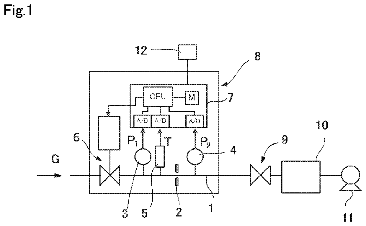
[0058]A pressure-type flow rate control device 8 has, for example, a configuration as illustrated in FIG. 1 and includes a restriction part 2 interposed in a flow passage 1, a control valve 6 interposed upstream of the restriction part 2 in the flow passage 1, an upstream pressure sensor 3 that is disposed between the restriction part 2 and the control valve 6 and detects an upstream pressure P1 of the restriction part 2, a downstream pressure sensor 4 that detects a downstream pressure P2 of the restriction part 2, a temperature sensor 5 that detects a temperature between the restriction part 2 and the control valve 6, and a controller 7. Unlike in the conventional pressure-type f...


PUM


Abstract

A pressure-type flow rate control device includes a restriction part, a control valve disposed upstream of the restriction part, an upstream pressure sensor, a downstream pressure sensor, and a controller that diagnoses flow rate control by using pressure drop data on a flow passage between the control valve and the restriction part and reference pressure drop data, wherein a close command is issued to the control valve and a shutoff valve provided downstream of the downstream pressure sensor, and the controller determines whether a predetermined critical expansion condition is satisfied by using outputs of the upstream pressure sensor and the downstream pressure sensor after the control valve is closed, and diagnoses flow rate control by using the pressure drop data acquired during a period in which the predetermined critical expansion condition is satisfied.

Description

TECHNICAL FIELD[0001]The present invention relates to a pressure-type flow rate control device used for, for example, semiconductor manufacturing facilities and chemical plants, and in particular to a pressure-type flow rate control device having a flow rate self-diagnostic function and to a flow rate self-diagnosis method.BACKGROUND ART[0002]A pressure-type flow rate control device 8 that, as illustrated in FIG. 1, includes a flow passage 1 that allows a fluid G that is to be controlled to pass through, a restriction part 2 such as an orifice plate that is interposed in the flow passage 1, an upstream pressure sensor 3 that detects an upstream pressure P1 of the restriction part 2, a downstream pressure sensor 4 that detects a downstream pressure P2 of the restriction part 2, a temperature sensor 5 that detects an upstream temperature T of the restriction part 2, a control valve 6 that is provided upstream of the upstream pressure sensor 3 in the flow passage 1, and a controller 7 ...

Claims


Application Information

Patent Timeline
Patent Type & Authority Patents(United States)
IPC IPC(8): G05B23/02G05D7/06
CPCG05B23/0264G05B23/0291G05D7/06G05D7/0635G05B23/0235
Inventor NAGASE, MASAAKIHIRATA, KAORUSAWADA, YOHEISUGITA, KATSUYUKINISHINO, KOUJIIKEDA, NOBUKAZU
Owner FUJIKIN INC
Why Eureka
Try Eureka