
Semiconductor device and semiconductor device manufacturing method

a semiconductor device and semiconductor technology, applied in the direction of semiconductor devices, basic electric elements, electrical appliances, etc., can solve the problems of reduced film thickness at the portion of tunnel insulation film covering the pointed portion of the floating gate, and deterioration of film quality, so as to prevent data deterioration in the memory cell

Active Publication Date: 2020-12-15
LAPIS SEMICON CO LTD
View PDF8 Cites 1 Cited by
  • Summary
  • Abstract
  • Description
  • Claims
  • Application Information

AI Technical Summary

Benefits of technology

This patent provides a semiconductor device and a manufacturing method that can prevent data in a memory cell from deteriorating. It does this by preventing etching of the side surface of a spacer.

Problems solved by technology

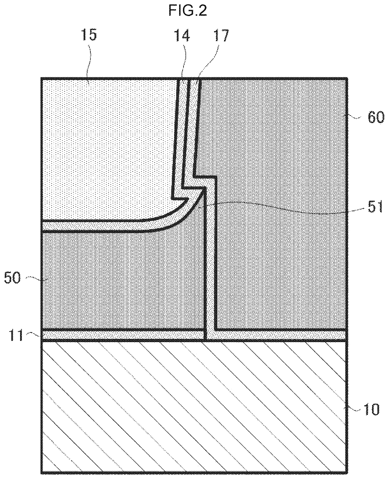
In the semiconductor memory manufacturing steps described above, the film thickness at the portion of the tunnel insulation film covering the pointed portion of the floating gate may be reduced or the film quality may deteriorate, due to etching of a side surface of the spacer during etching for removing the nitride film.

Method used


Image

  • Semiconductor device and semiconductor device manufacturing method
  • Semiconductor device and semiconductor device manufacturing method
  • Semiconductor device and semiconductor device manufacturing method

Examples


first exemplary embodiment

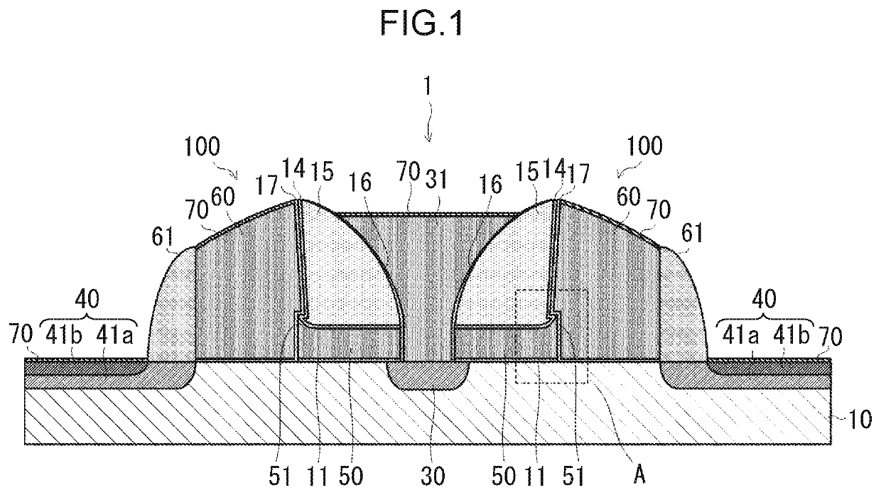
[0025]FIG. 1 is a cross-sectional view illustrating a configuration of a semiconductor device 1 according to a first exemplary embodiment of the disclosure. The semiconductor device 1 includes plural memory cell arrays, each including two split-gate memory cells 100. The two split-gate memory cells 100 share a source diffusion layer 30 and a source wiring 31, and are respectively disposed symmetrically about the source diffusion layer 30 and the source wiring 31 interposed in between.

[0026]Each of the memory cells 100 includes the source diffusion layer 30 and a drain diffusion layer 40 placed separately from each other in a surface of a semiconductor substrate 10. Further, each of the memory cells 100 includes a floating gate 50 and a control gate 60 provided on a surface of the semiconductor substrate 10 at an area between the source diffusion layer 30 and the drain diffusion layer 40. The semiconductor substrate 10 is formed of a material containing, for example, a monocrystallin...

second exemplary embodiment

[0060]FIG. 5 is a cross-sectional view illustrating a configuration of a semiconductor device 1A according to a second exemplary embodiment of the disclosure. Each memory cell 100A that configures the semiconductor device 1A is different from the semiconductor device 1 according to the first exemplary embodiment, in that the side surface of the spacer 15 is substantially vertical to a main surface of the semiconductor substrate 10, and the surface of the protective oxidized film 14 that covers the side surface of the spacer 15 and the side surface of the floating gate 50 extend in an identical plane.

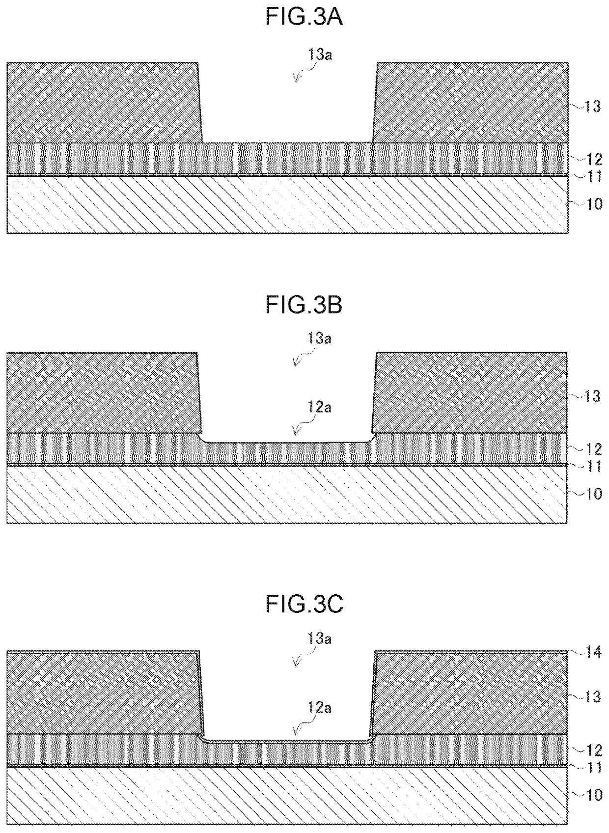
[0061]Referring to FIG. 6A to FIG. 6H, a manufacturing method of the semiconductor device 1A will be described below. The polysilicon film 12 that configures the floating gate 50 is formed at the surface of the semiconductor substrate 10 via the gate insulation film 11. Next, the nitride film 13 having the opening 13a is formed at the surface of the polysilicon film 12. The side surface ...


PUM

PropertyMeasurementUnit
thicknessaaaaaaaaaa
thicknessaaaaaaaaaa
voltageaaaaaaaaaa

Abstract

A semiconductor device including a memory cell, the semiconductor device including: a floating gate provided at a semiconductor substrate with a first insulation film inbetween, and including a pointed portion having a pointed end at one end side; a spacer provided at the floating gate; a second insulation film provided between the floating gate and the spacer and that covers a side surface of the spacer at the one end side; and a control gate that contacts a side surface of the floating gate at the one end side via a third insulation film and that contacts the side surface of the spacer at the one end side via the second insulation film and the third insulation film.

Description

CROSS-REFERENCE TO RELATED APPLICATION[0001]This application claims priority under 35 USC 119 from Japanese Patent Application No. 2017-198624, filed on Oct. 12, 2017, the disclosure of which is incorporated by reference herein.BACKGROUNDTechnical Field[0002]The present invention relates to a semiconductor device and a semiconductor device manufacturing method.Related Art[0003]A split-gate semiconductor memory is known as an electrically programmable read-only memory (EEPROM).[0004]For example, Japanese Patent Application Laid-Open (JP-A) No. 2008-251825 discloses a semiconductor device manufacturing method including: forming a conductive material layer for a floating gate on a semiconductor layer with a gate insulation film in between; forming a first spacer consisting of a first silicon dioxide film, and a second spacer adjacent to the first spacer, consisting of a second silicon dioxide film and having an etching rate lower than an etching rate of the first silicon dioxide film; ...

Claims


Application Information

Patent Timeline
Patent Type & Authority Patents(United States)
IPC IPC(8): H01L29/66H01L27/11521H01L29/423H01L21/311H01L21/28H01L21/02
CPCH01L21/31111H01L29/42324H01L29/66825H01L29/42328H01L27/11521H01L29/40114H01L21/02263H01L29/401H10B41/30
Inventor CHIBA, AKIRA
Owner LAPIS SEMICON CO LTD
Learn More