
Strain wave gearing

a gearing and strain wave technology, applied in the direction of gearing, toothed gearings, shafts and bearings, etc., can solve the problems of large rotational torque to generate wave motion and unsatisfactory effects, so as to reduce the reduce the effect of rotational torque of the wave generator

Active Publication Date: 2021-03-02
HARMONIC DRIVE SYST IND CO LTD
View PDF9 Cites 0 Cited by
  • Summary
  • Abstract
  • Description
  • Claims
  • Application Information

AI Technical Summary

Benefits of technology

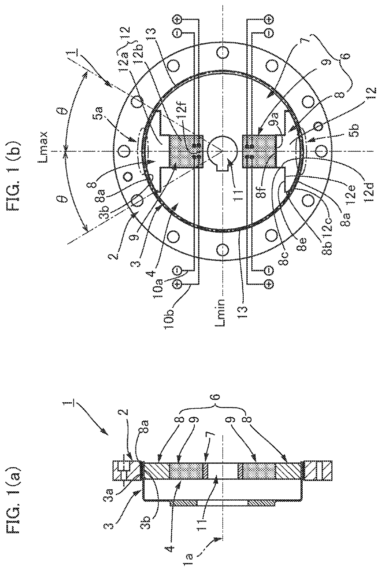
[0009]The respective gear pressing units of the wave generator press the flexible gear in the radial direction to flex in a state in which the pressing units are applied with ultrasonic vibration. In a case of a sliding-contact type wave generator, for example, ultrasonic vibration of 20 kHz to 80 kHz is applied to the sliding-contact parts between the gear pressing unit and the flexible gear. As a result of a squeeze film effect, the apparent frictional coefficient at the contact surface of each sliding-contact part can be greatly reduced. In addition, the ultrasonic vibration is transmitted to a meshing portion between the flexible gear and the rigid gear, and the apparent frictional coefficient at the meshing tooth surface can be greatly reduced. Accordingly, rotational torque of the wave generator can be reduced.
[0012]In this case, the gear pressing members may be assembled to the plug body member so as to form a state in which the reaction force from the elliptically flexed externally toothed gear is applied to the piezoelectric members as a preliminary load. This makes it possible to form a structure to avoid the piezoelectric elements from being applied with external force in the form of tensile force.
[0013]The elliptical rigid plug is provided on the both ends in the major-axis direction with the gear pressing members, a circumferential length of the outer peripheral surface of which can be such that it extends across an angle of 30 degrees to 40 degrees left and right from the major axis, preferably 35 degrees. In the consideration of the radial load distribution of the strain wave gearing during load is being applied, a large radial load is applied to the area within an angular range of approximately 35 degrees left and right from the major axis. The ultrasonic vibration in the major-axis direction can be applied to the area where the radial load is large, whereby the rotational torque of the wave generator can be effectively reduced. In addition, at the side of the plug body member that supports the gear pressing members in a slidable manner, it is possible to provide sufficient guide parts to guide the gear pressing members in the major-axis direction in a reliable manner.
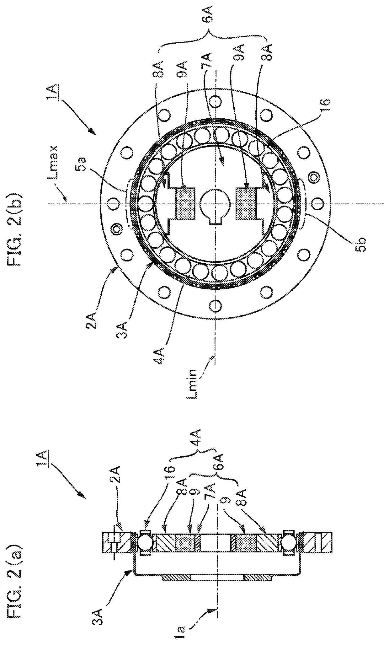
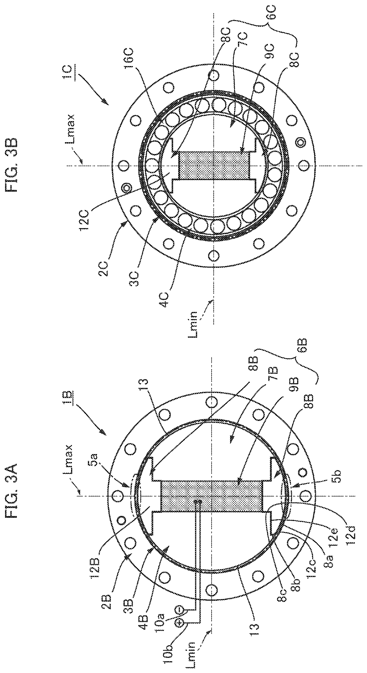
[0014]Next, the present invention can also be applied to a strain wave gearing provided with a wave generator that is in rolling-contact with a flexible gear. For example, a wave generator, which flexes a flexible externally toothed gear into an elliptical shape to mesh partially with a rigid internally toothed gear, is provided with a rotating body (which is a plug or a cam plate) and a rolling bearing mounted between an inner peripheral surface of the externally toothed gear and an elliptical outer peripheral surface of the rotating body. In this case, in the respective portions along the major-axis direction of the strain wave gearing, component parts are in contact with each other in both operations load being applied and no-load being applied, and therefore ultrasonic vibration in the major-axis direction is transmitted to the respective portions (including a raceway part of a rolling bearing of the wave generator, an outer race of the rolling bearing and an inner peripheral surface of the internally toothed gear, and tooth surfaces). Thus, even in a strain wave gearing provided with a rolling-contact type wave generator, in which wave motion is generated by making balls or rollers to roll along the elliptical outer peripheral surface of the rotating body, it is possible to reduce rotational torque of the wave generator.

Problems solved by technology

The sliding-contact type wave generator has an advantage that viscous resistance in rotation is small and an input torque hardly changes even if input rotational speed is changed, but has a disadvantage that a rotational torque to generate the wave motion is large.
However, satisfied effects have not been obtained.

Method used


Image

  • Strain wave gearing
  • Strain wave gearing
  • Strain wave gearing

Examples


Embodiment Construction

[0022]Embodiments of a strain wave gearing according to the present invention will be described with reference to the drawings. The following embodiments relate to a cup-type strain wave gearing. The present invention can also be applied to a silk-hat type strain wave gearing and a flat-type strain wave gearing in a similar manner.

[0023]FIG. 1(a) is a schematic longitudinal cross-sectional view of a strain wave gearing according to an embodiment of the present invention, and FIG. 1(b) is a schematic end view thereof. A strain wave gearing 1 is provided with an annular rigid internally toothed gear 2 (rigid gear), a cup-shaped flexible externally toothed gear 3 (flexible gear) disposed coaxially inside the internally toothed gear, and a wave generator 4 fitted coaxially into the externally toothed gear. The internally toothed gear 2 and the externally toothed gear 3 are supported by a not-shown support member in a relatively rotatable state about a device center axis line 1a. The ext...


PUM


Abstract

A strain wave gearing has a rigid internally toothed gear, a flexible externally toothed gear, and a sliding-contact type wave generator. The wave generator has: a plurality of gear pressing members that flexes the externally toothed gear in the radial direction at positions at equal angular intervals in the circumferential direction to form plurality of meshing portions which mesh with the internally toothed gear; and piezoelectric elements that generate ultrasonic vibration of 20 kHz to 80 kHz in the gear pressing members in the radial direction. Ultrasonic vibration is applied at contact sites where the gear pressing members and the externally toothed gear contact each other. As a result of a squeeze film effect, the apparent friction coefficient of each contact surface at the contact sites can be greatly reduced and rotational torque, of the wave generator can be reduced.

Description

TECHNICAL FIELD[0001]The present invention relates to a strain wave gearing, and, in particular, to a strain wave gearing which can reduce rotational torque of a wave generator for generating a wave motion in a flexible gear.BACKGROUND ART[0002]A strain wave gearing is generally configured so that a wave generator causes to generate a wave motion in a flexible externally toothed gear disposed inside a rigid internally toothed gear and relative rotation is generated between the gears in accordance with the difference in the number of teeth therebetween. A rolling-contact type wave generator is employed as a wave generator. A contact-rolling type wave generator is provided with a rotating body called as a plug or a cam plate having an elliptical contour, the rotating body being mounted inside the externally toothed gear via a rolling bearing. The externally toothed gear is flexed elliptically along the elliptical contour of the rotating body and is meshed with the internally toothed g...

Claims


Application Information

Patent Timeline
Patent Type & Authority Patents(United States)
IPC IPC(8): F16H49/00F16H1/32F16H57/00
CPCF16H49/001F16H1/32F16H57/0006F16C33/30
Inventor KOBAYASHI, MASARU
Owner HARMONIC DRIVE SYST IND CO LTD
Learn More