Waste compaction system for a vehicle and cabin monument with such a waste compaction system

vehicle technology, applied in the field of waste compaction system for vehicle and cabin monument with such a waste compaction system, can solve the problems of waste products, and achieve the effects of reducing weight and complexity, preventing excessive liquid leakage, and reducing was

Active Publication Date: 2021-03-09
AIRBUS OPERATIONS GMBH
View PDF11 Cites 0 Cited by
  • Summary
  • Abstract
  • Description
  • Claims
  • Application Information

AI Technical Summary

Benefits of technology

[0012]A peculiarity of the trolley can be seen in that it comprises an integrated vacuum compaction mechanism that compacts the waste products collected in the trolley in a particularly effective fashion by applying a vacuum such that these waste products are compressed to a fraction of their original volume in the compaction sheath. The compression effect caused by the vacuum is also significantly intensified due to the use of the at least one rigid plate, preferably two paired rigid plates, because a deformation thereof during the compaction process may practically be ruled out such that the compaction sheath does not form any local bulges and the compressive force is very evenly applied to the waste products. A particularly high compaction force can be achieved by essentially using the entire available surface. The larger the surface of the rigid plates used for the compaction, the higher the force acting upon the waste products.
[0036]The cabin monument may furthermore comprise at least one lavatory that is coupled to the suction line. In an aircraft, in particular, the lavatory is connected to a vacuum system that may dispose liquids and waste products in a particularly reliable and mechanically simple fashion. The suction line provided in such a vacuum system may be easily coupled to the waste compaction system according to the invention in order to carry out a compaction.

Problems solved by technology

Foods and beverages are frequently consumed aboard means of transportation that serve for transporting passengers and result in waste products.

Method used


Image

  • Waste compaction system for a vehicle and cabin monument with such a waste compaction system
  • Waste compaction system for a vehicle and cabin monument with such a waste compaction system
  • Waste compaction system for a vehicle and cabin monument with such a waste compaction system

Examples


Embodiment Construction

[0046]The following detailed description is merely illustrative in nature and is not intended to limit the embodiments of the subject matter or the application and uses of such embodiments. As used herein, the word “exemplary” means “serving as an example, instance, or illustration.” Any implementation described herein as exemplary is not necessarily to be construed as preferred or advantageous over other implementations. Furthermore, there is no intention to be bound by any expressed or implied theory presented in the preceding technical field, background, brief summary or the following detailed description.

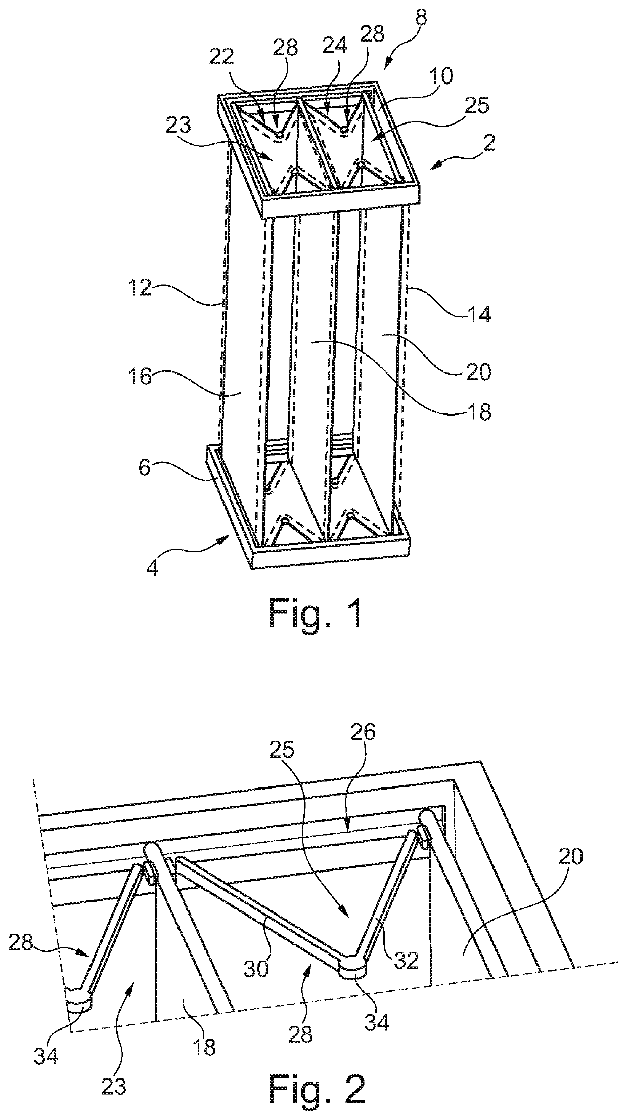
[0047]FIG. 1 shows a trolley 2 of a waste compaction system in the form of a schematic three-dimensional representation that is highly simplified due to the partial omission of a housing. This figure shows a bottom 4 that comprises an exemplary frame 6 carrying not-shown rollers for the movement on the floor and a cover plate, a closable opening or the like as a delimitation fro...


PUM


Abstract

A waste compaction system includes a trolley for collecting waste and a docking station that is integratable into a cabin monument of a vehicle. The trolley includes a housing with chambers for waste, an opening for introducing waste, a vacuum compaction mechanism assigned to a chamber, and a suction port accessible from outside the housing and couplable to the compaction mechanism. The compaction mechanism includes a compaction sheath extending from a bottom of the housing to a frame arranged opposite the bottom, and is fillable through the opening, and a rigid plate is arranged on or in at least one lateral surface of the compaction sheath and moves together with the compaction sheath during the evacuation thereof. The docking station and the trolley mate with each other. The docking station includes another suction port that is couplable to a suction line in the vehicle and the first suction port.

Description

CROSS-REFERENCE TO PRIORITY APPLICATIONS[0001]This application is a continuation of international patent application number PCT / EP2016 / 062001, having an international filing date of May 27, 2016, which claims priority to German patent application number DE 102015108442.2, having a filing date of May 28, 2015. The content of the referenced applications is incorporated by reference herein.TECHNICAL FIELD[0002]Embodiments of the invention pertain to a waste compaction system for a means of transportation, a cabin monument with such a waste compaction system, as well as a means of transportation, particularly an aircraft, that comprises a cabin and at least one such waste compaction system.BACKGROUND[0003]Foods and beverages are frequently consumed aboard means of transportation that serve for transporting passengers and result in waste products. Aboard passenger aircraft, in particular, these waste products are predominantly collected by the cabin personnel and have to be disposed afte...

Claims


Application Information

Patent Timeline
Patent Type & Authority Patents(United States)
IPC IPC(8): B64D11/04B64D11/02B65F1/14B64D11/00
CPCB64D11/04B64D11/00B64D11/02B65F1/1405B65F1/1473B65F2210/132B65F2210/168B65F2210/188
Inventor SCHLIWA, RALFSPILLE, MARC
Owner AIRBUS OPERATIONS GMBH
Why Eureka
Try Eureka