Hybrid transfer machine

a transfer machine and hybrid technology, applied in the direction of transfer printing, printing, textile parts treatment, etc., can solve the problems of excessive setting time, increased operating cost, and reduced efficiency of space utilization, and achieve the effect of improving operability

Active Publication Date: 2021-03-16
KYUNGIL TECH
View PDF17 Cites 0 Cited by
  • Summary
  • Abstract
  • Description
  • Claims
  • Application Information

AI Technical Summary

Benefits of technology

[0009]The present invention has been conceived to overcome the above-described problems, and an object of the present invention is to provide a hybrid transfer machine having improved operability, which can be used for both a roll-type purpose and a piece-type purpose and also enables an initial setting operation to be rapidly and conveniently performed.

Problems solved by technology

Meanwhile, conventionally, it is necessary to separately purchase a roll-type transfer machine and a piece-type transfer machine, and thus the operating cost increases.
Furthermore, the two machines are disposed within the same space, and thus the efficiency of space utilization is considerably reduced.
Meanwhile, in the case of conventional transfer machines, transfer paper must be connected with tissue and fabric via a narrow gap from the outside, and thus an initial setting operation is not only significantly inconvenient, but also setting time is excessively long, thereby causing a fundamental problem in that operability is considerably degraded.

Method used


Image

  • Hybrid transfer machine
  • Hybrid transfer machine
  • Hybrid transfer machine

Examples


first embodiment

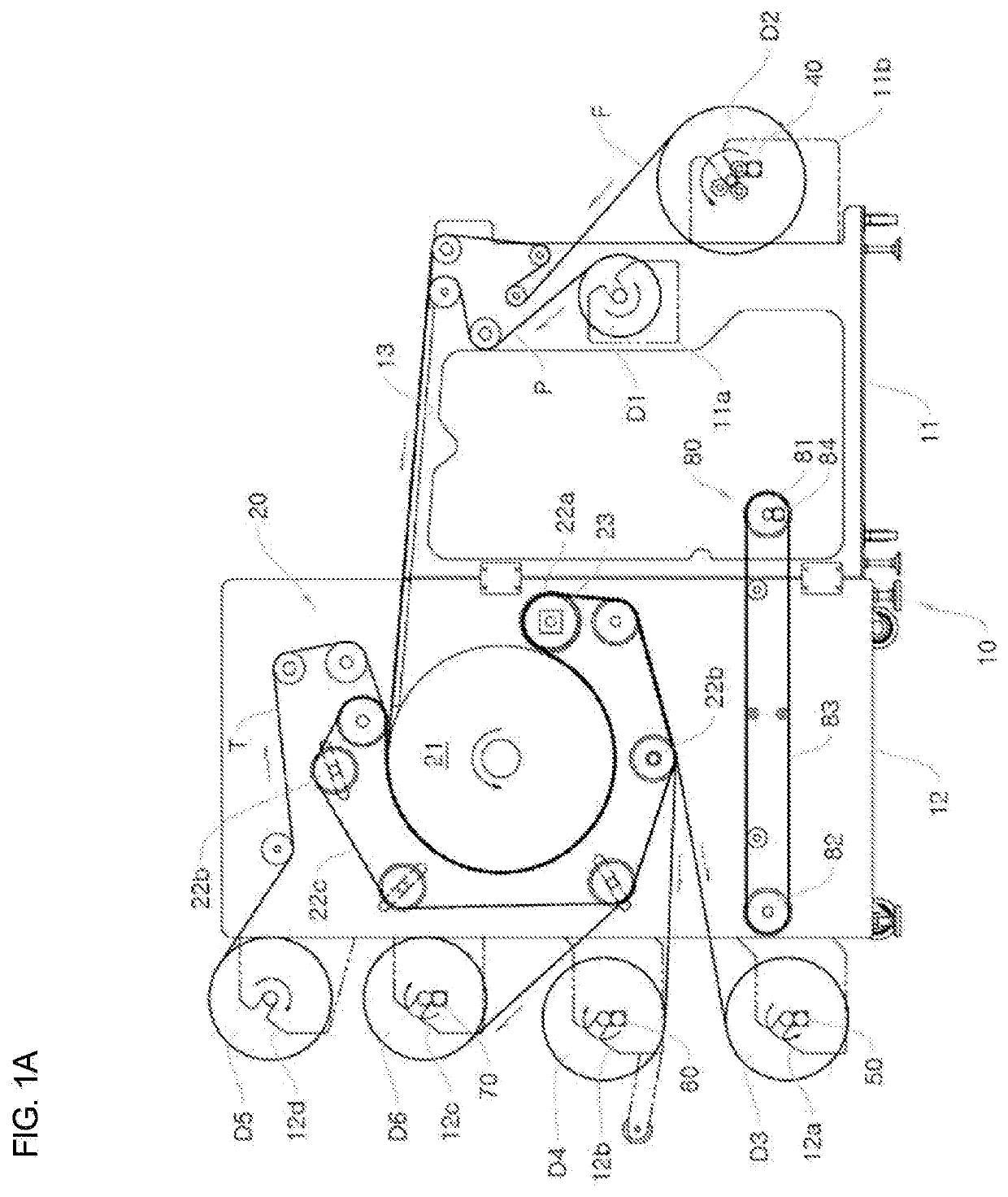
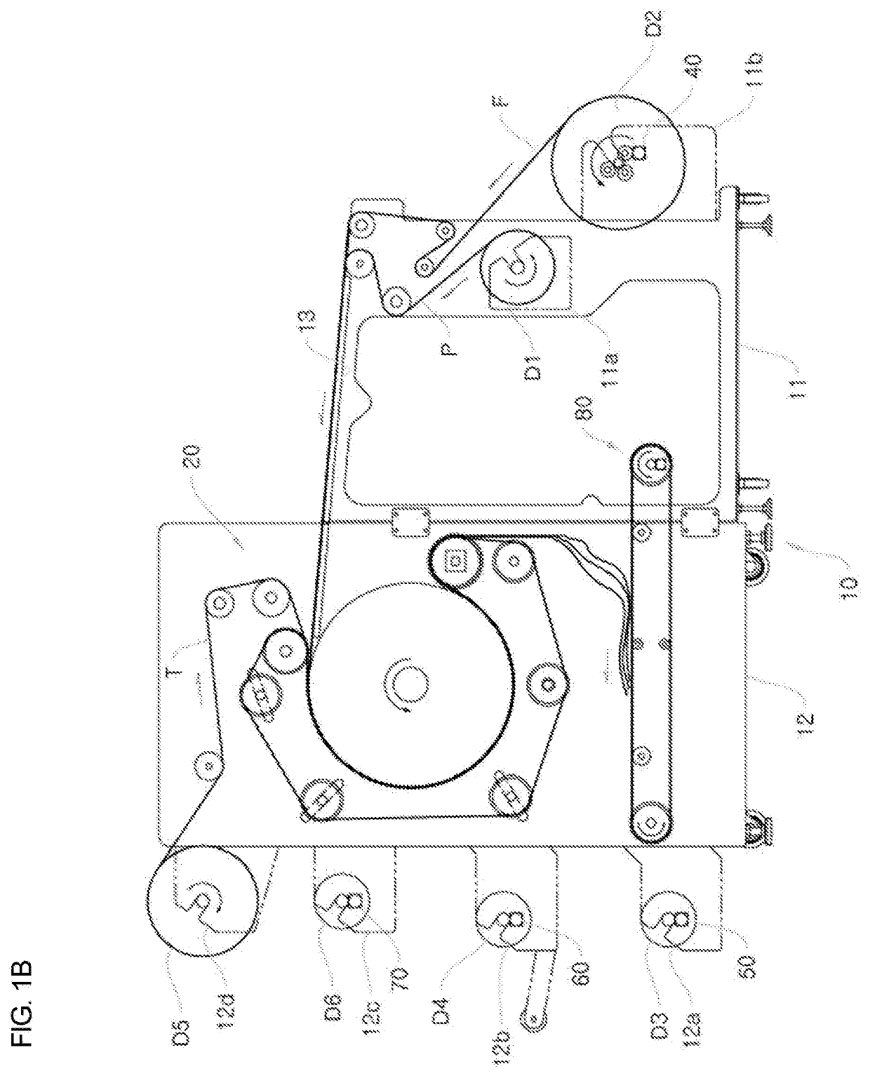
[0099]FIG. 4A is a front view showing a hybrid transfer machine according to a first piece-type embodiment of the present invention, and FIG. 4B is a view illustrating a preparation process of FIG. 4A.

[0100]The configuration of the first piece-type embodiment is the same as the first roll-type embodiment only except that a piece-type roller arm 30 is applied to the first embodiment of a piece type.

[0101]The piece-type roller arm 30 is installed in the fourth drum installation part 12b of a second body 12 in the form of a cantilever, and functions to guide transfer paper P, fed from a thermal transfer unit 20, to a transfer paper take-up drum D3 rotatably installed in a third drum installation part 12a.

[0102]As an example, transfer paper P, each piece of fabric F′, and tissue T (which may be omitted as desired) are discharged from the thermal transfer unit 20 in a superimposed state, and are separated from each other at a specific location (see FIGS. 4A and 4B). The transfer paper P...

second embodiment

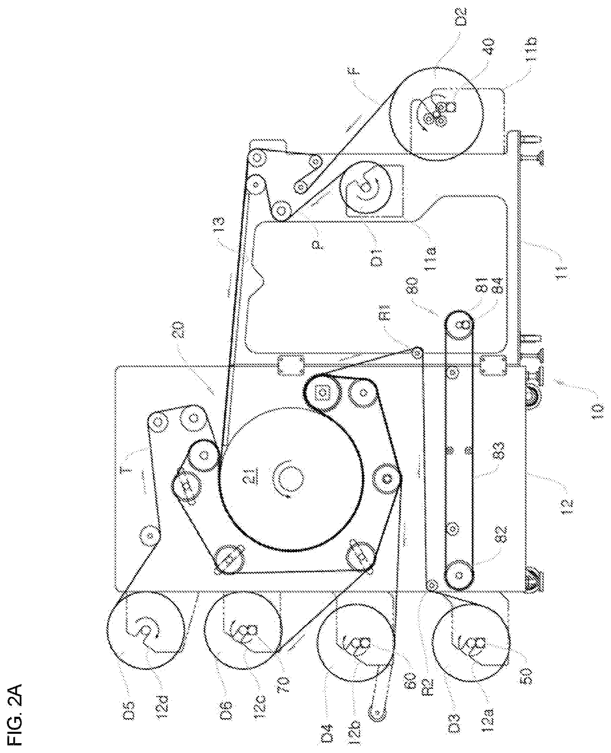
[0116]FIG. 5A is a front view showing a hybrid transfer machine according to a second piece-type embodiment the present invention, and FIG. 5B is a view illustrating the preparation process of FIG. 5A.

[0117]The overall configuration of the second pieces-type embodiment is the same as that of the first piece-type embodiment only except that a third roller R3 is further included in the second piece-type embodiment.

[0118]The third roller R3 is rotatably installed in a first body 11 to be adjacent to a worktable 13, and functions to guide transfer paper P, exiting from a thermal transfer unit 20, to a first roller R1.

[0119]As an example, the transfer paper P, a piece of fabric F′, and tissue T (which may be omitted as desired) are discharged from the thermal transfer unit 20 in a superimposed state.

[0120]Meanwhile, when they are moved in the superimposed state for a long period of time, the transfer paper P and the piece of fabric F′ are shaken due to vibrations during movement accordin...

third embodiment

[0123]FIG. 6A is a front view showing a hybrid transfer machine according to a third piece-type embodiment of the present invention, and FIG. 6B is a view illustrating a preparation process of FIG. 6A.

[0124]The overall configuration of the third embodiment is the same as that of the second embodiment only except that a fourth roller R4 and a fifth roller R5 are further included in the third embodiment.

[0125]The fourth roller R4 is rotatably installed between a third roller R3 and a conveyer 80 in a first body 11, and functions to guide transfer paper P, guided by the third roller R3, to a transfer paper take-up drum D3.

[0126]The fifth roller R5 is rotatably installed between the third roller R3 and the fourth roller R4 inside the first body 11, and functions to guide tissue T, exiting from a thermal transfer unit 20, to a tissue take-up drum D6.

[0127]As an example, the transfer paper P, a piece of fabric F′, and tissue T are discharged from the thermal transfer unit 20 in a superimp...


PUM

PropertyMeasurementUnit
temperatureaaaaaaaaaa
circumferenceaaaaaaaaaa
poweraaaaaaaaaa

Abstract

A hybrid transfer machine includes: a body including a first drum installation part, a second drum installation part, a first body, a second body, and a worktable; a first drive means configured to allow wound fabric to be unwound; a thermal transfer unit configured to be installed in the second body, and to press and heat the fabric and transfer paper; a piece-type roller arm configured to be installed in the second body, and to guide the transfer paper to the third drum installation part; a second drive means configured to allow the transfer paper to be wound; a third drive means configured to allow the fabric to be wound; and a conveyer configured to be installed in the body, and to transfer the fabric and the transfer paper to the third and fourth drum installation parts.

Description

CROSS REFERENCE[0001]This application claims foreign priority under Paris Convention to Korean Patent Application No. 10-2017-0101626, filed 10 Aug. 2017, with the Korean Intellectual Property Office, the entirety of which is incorporated herewith.BACKGROUND[0002]The present invention relates to a hybrid transfer machine having improved operability, which can be used for both a roll-type purpose and a piece-type purpose and also enables an initial setting operation to be rapidly and conveniently performed.[0003]Generally, designs are printed on fabrics, such as handkerchiefs, clothes, etc., chiefly using a transfer printing method.[0004]A transfer printing method is designed to transfer the design of transfer paper onto fabric by placing the transfer paper having a specific design, a photo, or the like on the print target fabric and then moving a heating roller, the transfer paper, and the fabric in one direction in the state of pressing both the transfer paper and the fabric with t...

Claims


Application Information

Patent Timeline
Patent Type & Authority Patents(United States)
IPC IPC(8): B41F16/00B41F16/02B41M1/26B41M5/025D06B11/00
CPCB41F16/00B41F16/006B41F16/0026B41F16/02B41M1/26B41M5/025D06B11/0076B41F13/0024B41F16/002
Inventor JUNG, SOON TAE
Owner KYUNGIL TECH
Why Eureka
Try Eureka