
Rotary catheter drive unit containing seal-sets

a technology of rotary catheters and drive units, which is applied in the field of rotary catheters, can solve the problems of slowness, traumatic and expensive of prior art mechanical devices, and the narrow range of vessel diameters of narrower mechanical devices, and achieve the effect of quick break down of obstructions to particles

Active Publication Date: 2021-03-23
SHIBER SAMUEL
View PDF56 Cites 0 Cited by
  • Summary
  • Abstract
  • Description
  • Claims
  • Application Information

AI Technical Summary

Benefits of technology

The solution enables quick breakdown of obstructions into particles, effective aspiration, and reduced risk of thermal injury or perforation, allowing for efficient treatment of varying vessel diameters and obstructions with improved mechanical and pharmaceutical co-action.

Problems solved by technology

Prior art mechanical devices are often limited to treating a narrow range of vessel diameters and a certain type of obstruction.
However, the diameter and the nature of the obstruction often varies along the diseased vessel, requiring multiple sizes and different kinds of prior art devices in a single clinical case.
Furthermore, each of such prior art devices can be slow, traumatic and expensive.
However, as the abrasive tip of these devices grinds through a small vessel or through a hard obstruction material, even if the tip is mounted eccentrically on the shaft, it is forced to rotate in an opening that is not larger than the tip, which the tip essentially blocks.
This prevents aspiration and cooling fluid or drugs from reaching the sides and the distal end of the tip, which may quickly cause thermal injury and / or perforation of the vessel wall.
However such drugs may take a long time, especially in the case of a long obstruction.
), but such systems are relatively cumbersome, expensive and address primarily soft obstructions.

Method used


Image

  • Rotary catheter drive unit containing seal-sets
  • Rotary catheter drive unit containing seal-sets
  • Rotary catheter drive unit containing seal-sets

Examples


Embodiment Construction

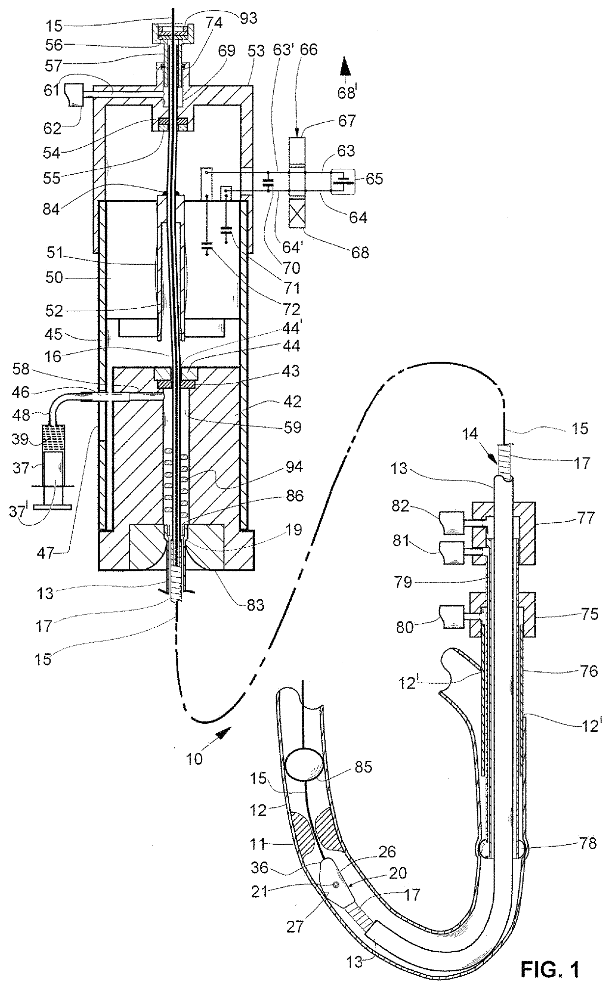
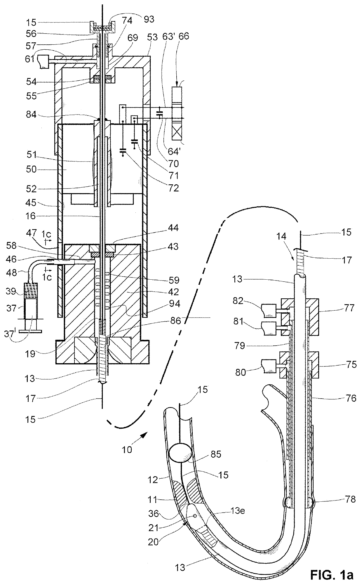
[0042]The rotary catheter can be inserted into a vessel directly, e.g., when access to a vessel is gained surgically, or through the skin via an introducer. The introducer can also be used to inject fluids, such as saline, with drugs and radiopaque contrast agent into the vessel, which, together with blood, keeps the obstruction particles suspended so that they can be readily aspirated. An optional guiding catheter can be used when the rotary catheter has to be guided further into the vessel. The guiding catheter can incorporate a proximal embolic barrier for temporarily blocking flow through the vessel, while the rotary catheter macerates and aspirates the obstruction material, thereby reducing the likelihood of releasing particles and drugs downstream. A distal embolic protection device can also be employed for the same purpose and, when the rotary catheter is used in a limb, an external pressure cuff can be utilized to temporarily stop circulation in the affected limb.

[0043]The f...


PUM

PropertyMeasurementUnit
diameteraaaaaaaaaa
flexibleaaaaaaaaaa
elastomericaaaaaaaaaa

Abstract

A motor drive for a rotary medical device having at least one seal-set which comprises a bore defining bearing, a motor having an output shaft, a flexible shaft, having a diameter smaller than the bearing's bore, being power transmittingly and concentrically connected to the output shaft, a seal, defining a bore that is smaller than the flexible shaft's diameter, being mounted adjacent to the bearing with its bore concentric relative with the bearing's bore, wherein the flexible shaft passing through the bearing's bore which sufficiently deflects it to align it with the second bore to interferencingly fit through it and hydraulically seal it.

Description

CROSS REFERENCE TO RELATED APPLICATIONS[0001]The application is a continuation and priority is claimed to commonly assigned, U.S. Patent Application:[0002]Ser. No. 15 / 598,958 by Shiber, entitled “ROTARY CATHETER DRIVE UNIT CONTAINING SEAL-SETS”, filed May 18, 2017, which claims priority to U.S. patent application Ser. No. 14 / 568,014 by Shiber, entitled “ROTARY CATHETER DRIVE UNIT CONTAINING SEAL-SETS”, filed Dec. 11, 2014, which claims priority to: 1) U.S. patent application Ser. No. 13 / 695,232 by Shiber, entitled “ROTARY CATHETER FOR REMOVING OBSTRUCTIONS FROM BODILY VESSELS”, filed on Jan. 8, 2013, which claims priority from Pat. Appl. PCT / US2011 / 031197 filed on Apr. 5, 2011 by Shiber, and entitled “ROTARY CATHETER FOR REMOVING OBSTRUCTIONS FROM BODILY VESSELS”, which further claims priority from U.S. Provisional Pat. Appl. Ser. No. 61 / 343,796, filed on May 4, 2010 by Shiber and entitled “THROMBECTOMY AND ATHERECTOMY CATHETER” and U.S. Provisional Pat. Appl. 61 / 461,263 filed on Ja...

Claims


Application Information

Patent Timeline
Patent Type & Authority Patents(United States)
IPC IPC(8): A61B17/22A61B17/3207B23B35/00A61B17/32A61B17/00B23B47/28
CPCA61B17/320758A61B17/22B23B35/00A61B2017/00336A61B2017/00734A61B2017/22038A61B2017/22048A61B2017/320044A61B2017/320766B23B47/28Y10T408/03A61B2017/22042A61B2017/22094A61B2017/320008A61B2217/007A61B2090/0801
Inventor SHIBER, SAMUEL
Owner SHIBER SAMUEL
Learn More