
Pillar unit for bio chip

a biochip and pillar technology, applied in the field of biochip pillar units, can solve the problems of inability to customize analysis by placing a relatively small number of samples at wider intervals or by, and achieve the effect of smooth radiation

Active Publication Date: 2021-03-23
MBD KOREA CO LTD
View PDF5 Cites 0 Cited by
  • Summary
  • Abstract
  • Description
  • Claims
  • Application Information

AI Technical Summary

Benefits of technology

The present invention provides a pillar unit for a bio chip that allows easy attachment and separation of samples. Additionally, the invention improves the light transmittance of the chip for better analysis of the samples. The substrate has penetration holes to ensure smooth radiation of the light source to the pillars.

Problems solved by technology

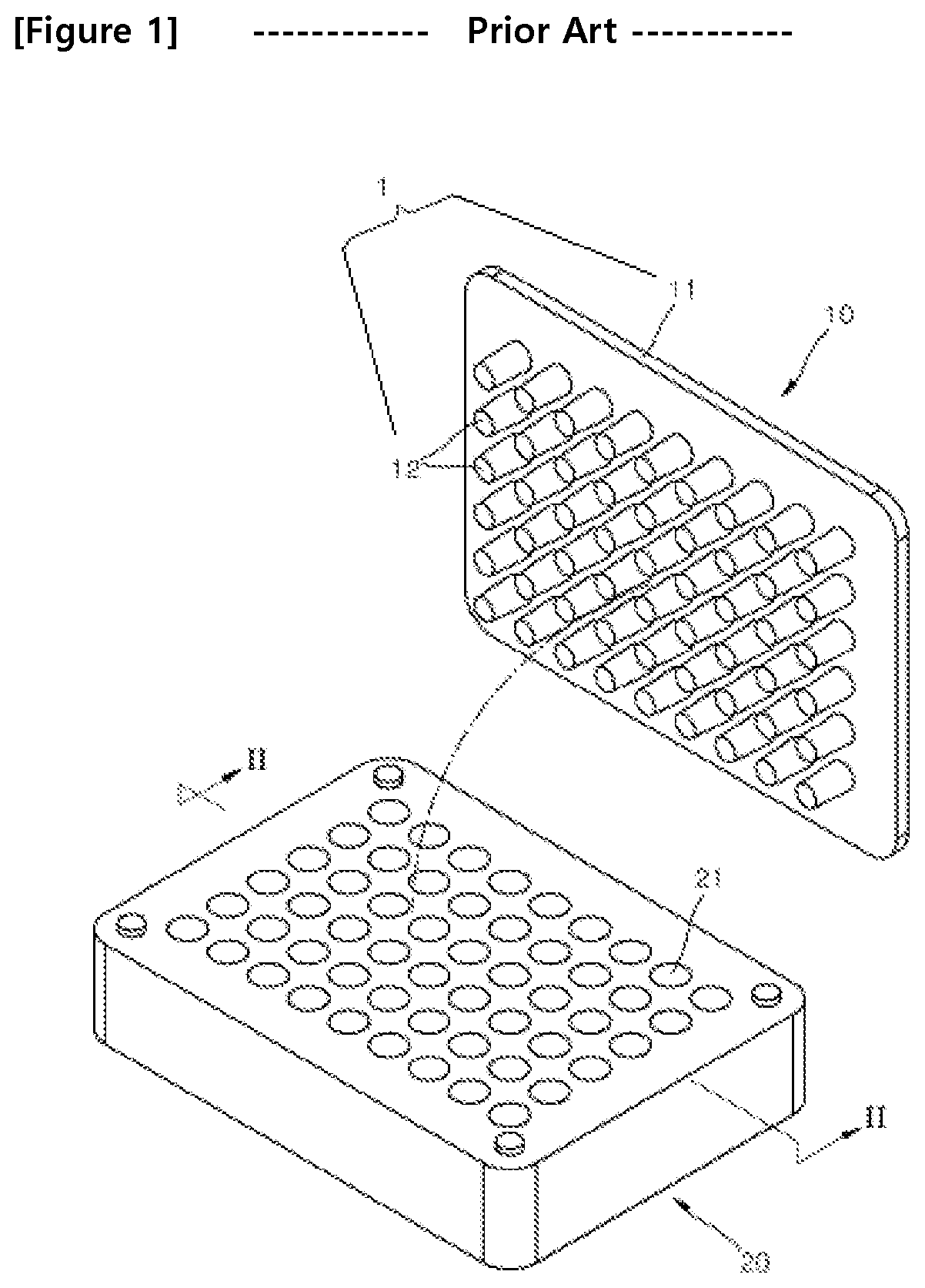
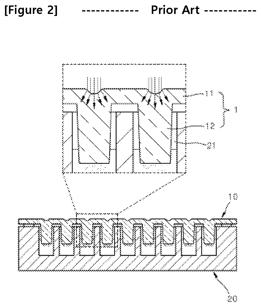
In such conventional bio chip, since all samples have to be analyzed at the same time at fixed pillar intervals, a customized analysis by placing a relatively small number of samples at wider intervals or by placing a large number of samples at narrow intervals may not be possible.

Method used


Image

  • Pillar unit for bio chip
  • Pillar unit for bio chip
  • Pillar unit for bio chip

Examples


Embodiment Construction

[0021]Hereinafter, a pillar unit for a bio chip according to an embodiment of the present invention will be described more fully with reference to the accompanying drawings.

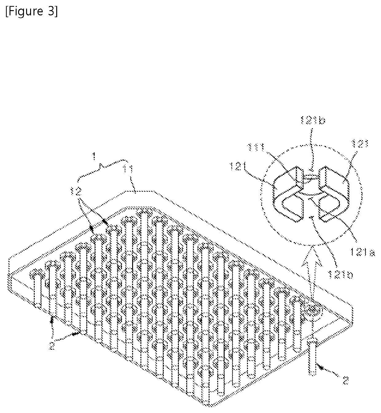
[0022]FIG. 3 is a perspective view of a pillar unit for a bio chip according to an embodiment of the present invention, FIG. 4 is a bottom view of the pillar unit of FIG. 3; and FIG. 5 is a cross-sectional view of the pillar unit of FIG. 3 cutting along V-V of FIG. 4.

[0023]As illustrated in the drawings above, the pillar unit for a bio chip according to an embodiment of the present invention is used to form a bio chip along with a well plate, in which a culture medium is accommodated, wherein the bio chip analyzes samples of biological micro-substances such as cells. The pillar unit is individually produced and includes a substrate 1 and pillars 2, both of which may be attached and detached.

[0024]As illustrated in FIG. 3, the substrate 1 includes a flat plate-form main body part 11 and a plurality of holder parts...


PUM

PropertyMeasurementUnit
shapeaaaaaaaaaa
lengthaaaaaaaaaa
mirror symmetryaaaaaaaaaa

Abstract

A pillar unit for a bio chip can include a plate-form substrate having a plurality of holder parts, which are spaced apart from each other, and each of the plurality of holder parts includes a holding space, to which a pillar is inserted and fixed, in which each of the plurality of holder parts further includes a pair transformation slits so that the corresponding holder part may be transformed and restored while the pillar is accommodated in the holding space; and a plurality of pillars corresponding to the plurality of holder parts, each of the plurality of pillars is accommodated in the holding space in one of the plurality of holder parts, one end of each of the plurality of pillars is combined with one holder part among the plurality of holder parts and is detachable, and the other end of each of the pillars includes a sample.

Description

CROSS-REFERENCE TO RELATED PATENT APPLICATION[0001]This application claims the benefit of Korean Patent Application No. 10-2018-0011404, filed on Jan. 30, 2018, in the Korean Intellectual Property Office, the disclosure of which is incorporated herein in its entirety by reference.BACKGROUND OF THE INVENTION1. Field of the Invention[0002]The present invention relates to a pillar unit for a bio chip, and more particularly, to a pillar unit for a bio chip having an improved structure so that pillars, where samples to be analyzed are attached, may be easily combined with and separated from a substrate and light transmittance of a light source radiated to the sample may increase for analyzing the sample.2. Description of the Related Art[0003]A bio chip is a bio device or a bio element and is a biological microchip in which samples of biological micro-substances such as DNA, protein, and cells are disposed on a substrate and are analyzed in terms of genetic defect, protein distribution, a...

Claims


Application Information

Patent Timeline
Patent Type & Authority Patents(United States)
IPC IPC(8): C12M1/32G01N33/53B01L3/00C12M3/00C12M1/12C12M1/00
CPCC12M23/12B01L3/5085B01L3/50853C12M23/42C12M23/44C12M25/06C12M31/02G01N33/5302B01L2200/025B01L2200/028B01L2200/10B01L2300/046B01L2300/0819B01L2300/0829B01L2300/0893B01L9/523B01L2300/0848
Inventor KU, BOSUNG
Owner MBD KOREA CO LTD
Learn More