Inertial sensor
a sensor and sensor technology, applied in the field ofinertial sensors, to achieve the effect of less integration errors and high accuracy
- Summary
- Abstract
- Description
- Claims
- Application Information
AI Technical Summary
Benefits of technology
Problems solved by technology
Method used
Image

Examples
embodiment 1
[0046]The inertial sensor in Embodiment 1 will be described with reference to FIGS. 1 to 7. In Embodiment 1, in addition to an output of an angular rate, an example of the inertial sensor that outputs an angle to the outside will be described.
[0047]
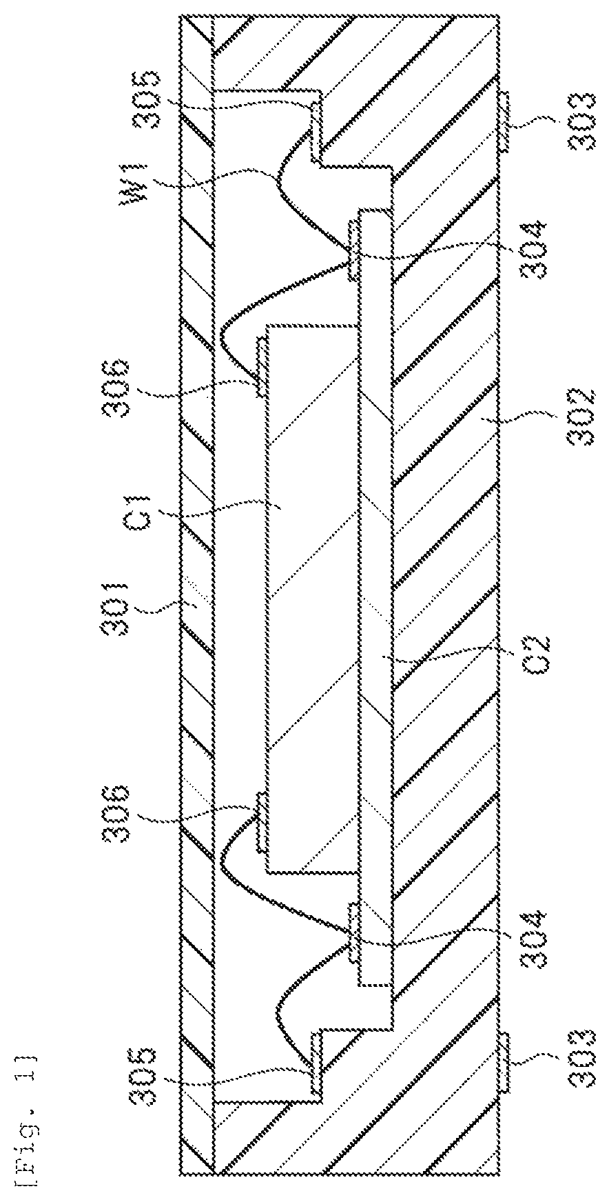
[0048]First, a structure of the inertial sensor in Embodiment 1 will be described with reference to FIG. 1. FIG. 1 is a sectional view illustrating an example of a structure of the inertial sensor.
[0049]In the inertial sensor in Embodiment 1, the angular rate detection element chip C1 (hereinafter, also referred to as an angular rate detection element) and the signal processing LSI chip C2 are provided in the sensor so that the angular rate can be detected. The angular rate detection element chip C1 is provided with a pad 306 on a main surface and is connected through the pad 306. The signal processing LSI chip C2 is provided with a pad 304 on a main surface and is connected through the pad 304.
[0050]In the inertial sensor illustrated in ...
embodiment 2
[0104]An inertial sensor in Embodiment 2 will be described with reference to FIGS. 8 to 10. In the following Embodiment 2, portions which are not mentioned in detail are the same as those in Embodiment 1. In Embodiment 2, an example of the inertial sensor that outputs acceleration to the outside in addition to the angular rate and the angle which are described above will be described.
[0105]FIG. 8 is a sectional view illustrating an example of a structure of the inertial sensor in Embodiment 2. In the inertial sensor in Embodiment 2, an angular rate detection element chip C1, an acceleration detection element chip C3 (hereinafter, also referred to as the acceleration detection element), and a signal processing LSI chip C4 are provided in the sensor so that the angular rate and the acceleration can be detected. The angular rate detection element chip C1 is provided with a pad 307 on a main surface and is connected through the pad 307. The acceleration detection element chip C3 is prov...
embodiment 3
[0117]An inertial sensor in Embodiment 3 will be described with reference to FIGS. 11 to 15. In the following Embodiment 3, portions which are not mentioned in detail are the same as those in Embodiment 1. In Embodiment 3, an example of the inertial sensor that outputs the angular rate of further one axis to the outside in addition to the angular rate of one axis which is described above will be described. Particularly, here, it is assumed that the angular rate of roll and pitch is detected. Moreover, a mechanical structure for detecting the angular rate may be three axes or more.
[0118]FIG. 11 is a sectional view illustrating an example of a structure of the inertial sensor in Embodiment 3. In the inertial sensor in Embodiment 3, angular rate detection element chips C5 and C6, and a signal processing LSI chip C7 are provided in the sensor so that the angular rate of two axes can be detected. The angular rate detection element chips C5 and C6 are provided with a pad 307 on a main sur...
PUM
 Abstract
Description
Claims
Application Information
 - R&D
- Intellectual Property
- Life Sciences
- Materials
- Tech Scout
- Unparalleled Data Quality
- Higher Quality Content
- 60% Fewer Hallucinations
Browse by: Latest US Patents, China's latest patents, Technical Efficacy Thesaurus, Application Domain, Technology Topic, Popular Technical Reports.
© 2025 PatSnap. All rights reserved.Legal|Privacy policy|Modern Slavery Act Transparency Statement|Sitemap|About US| Contact US: help@patsnap.com