
Lighting module and lighting apparatus having thereof

a technology of lighting module and lighting apparatus, which is applied in the field of lighting module to achieve the effect of improving backlighting characteristics and light extraction efficiency

Active Publication Date: 2021-03-23
LG INNOTEK CO LTD
View PDF17 Cites 0 Cited by
  • Summary
  • Abstract
  • Description
  • Claims
  • Application Information

AI Technical Summary

Benefits of technology

[0023]An embodiment of the invention may provide a lighting module in which light extraction efficiency and backlighting characteristics are improved.

Problems solved by technology

However, since an emitting angle of light emitted from an LED is small, when the LED is used as a vehicle lamp, it is required to increase a light emitting area of a lamp using the LED.

Method used


Image

  • Lighting module and lighting apparatus having thereof
  • Lighting module and lighting apparatus having thereof
  • Lighting module and lighting apparatus having thereof

Examples


first embodiment

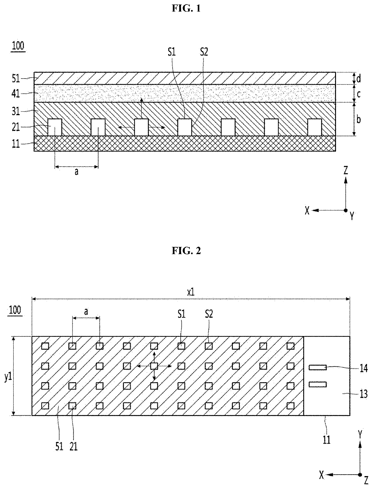
[0090]FIG. 1 is a side cross-sectional view illustrating a lighting module according to a first embodiment, and FIG. 2 is an example of a plan view of the lighting module of FIG. 1.

[0091]Referring to FIGS. 1 and 2, a lighting module 100 may include a substrate 11, a light emitting device 21 disposed on the substrate 11, a first resin layer 31 covering the light emitting device 21 on the substrate 11, and at least one or more of upper layers 41 and 51 on the first resin layer 31.

[0092]The lighting module 100 may emit light emitted from the light emitting device 21 to a surface light source. The lighting module 100 may include a reflection member disposed at an upper surface of the substrate 11. The reflection member may reflect light traveling to the upper surface of the substrate 11 to the first resin layer 31. The light emitting device 21 may be disposed on the substrate 11 in plural. In the lighting module 100, a plurality of light emitting devices 21 may be arranged in N columns ...

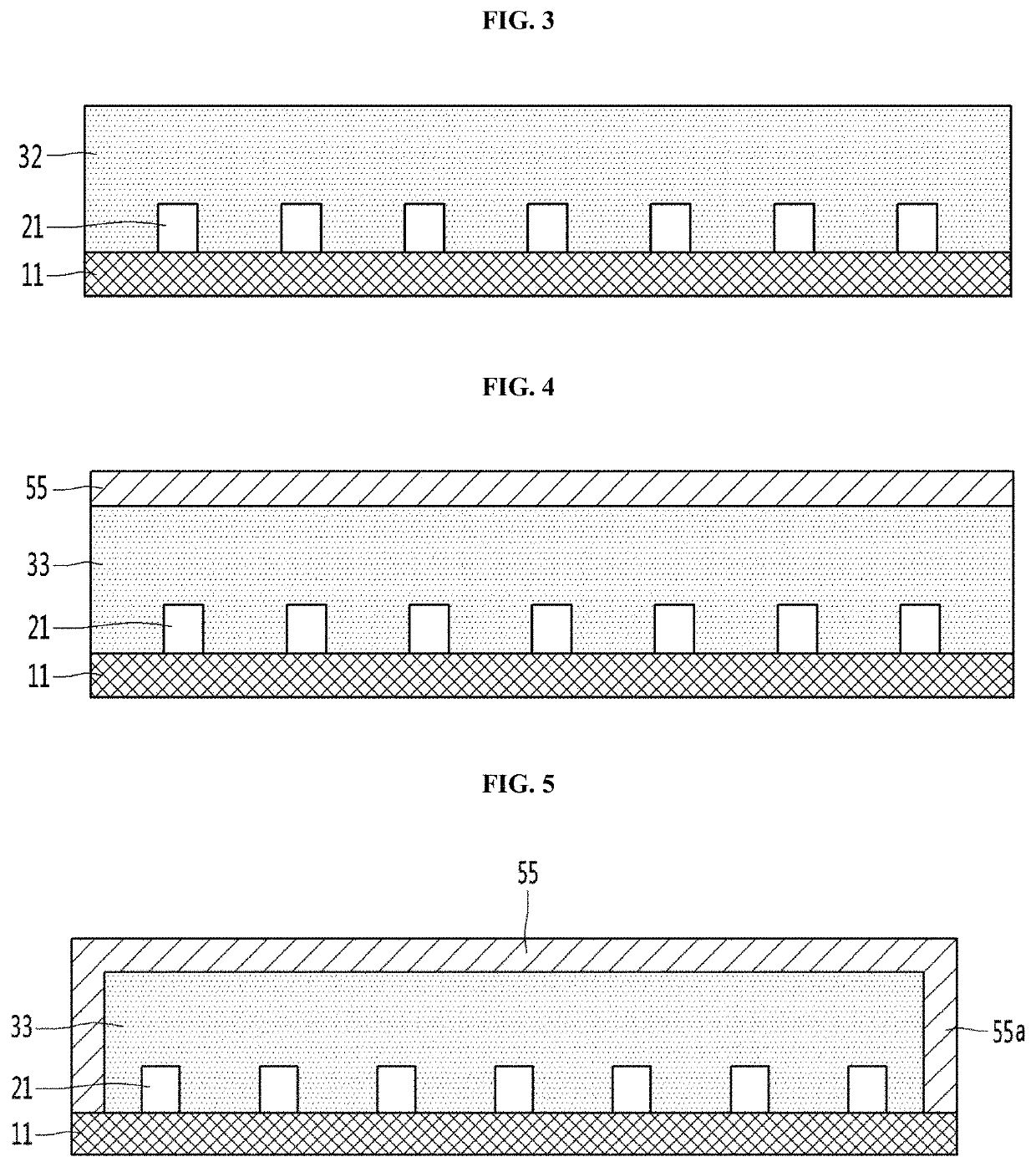
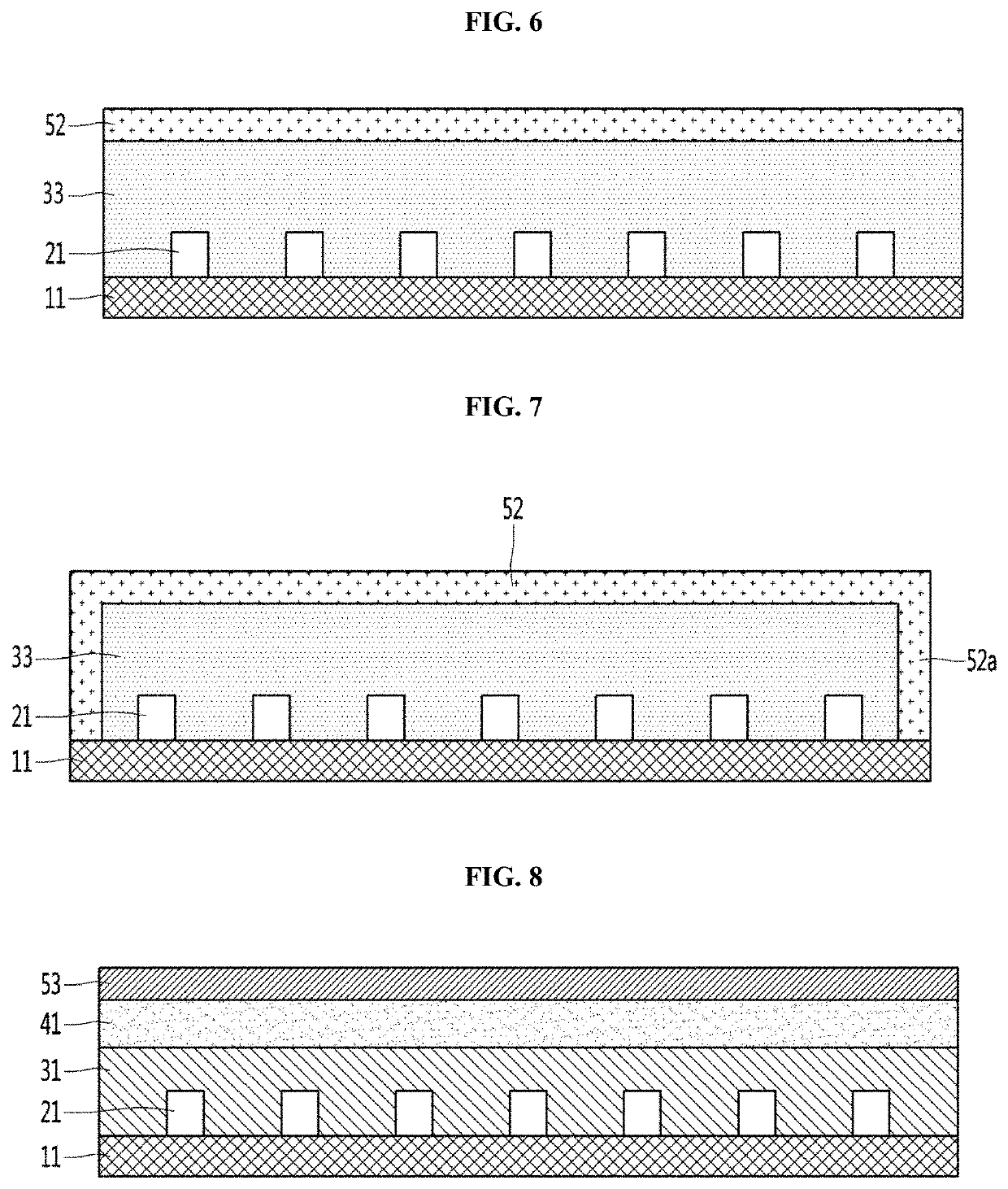
second embodiment

[0182]In describing the second embodiment, redundant description of the same configuration as that of the first embodiment will be omitted, and the same configuration as that of the first embodiment will refer to the first embodiment. The lighting module according to the second embodiment may include one or a plurality of resin layers on the light emitting device and the substrate. The resin layer may include, for example, one or more layers or two or more layers. The resin layer may optionally include at least two or three or more layers among an impurity-free layer, a layer to which a phosphor has been added, a layer having a diffusing agent, a layer to which ink particles have been added, a layer to which a phosphor and a diffusing agent have been added, and a layer to which a phosphor and ink particles have been added. The impurities may include a phosphor, a diffusing agent, or ink particles. At least one of the plurality of resin layers may optionally include at least one of a...


PUM

PropertyMeasurementUnit
sizeaaaaaaaaaa
refractive indexaaaaaaaaaa
wavelengthaaaaaaaaaa

Abstract

A lighting module according to an embodiment of the invention includes: a substrate; a plurality of light emitting devices disposed in N rows (N is an integer of 1 or more) on the substrate; a first resin layer covering the plurality of light emitting devices; a first diffusion layer disposed on the first resin layer and diffusing light emitted from the first resin layer; and a second diffusion layer disposed on the first diffusion layer and diffusing light emitted from the first diffusion layer, wherein the first diffusion layer includes a diffusing agent, and the second diffusion layer includes at least one of a phosphor and ink particles.

Description

CROSS-REFERENCE TO RELATED APPLICATIONS[0001]The present application claims priority under 35 U.S.C. § 119(a) of Korean Patent Application No. 10-2017-0123558 filed on Sep. 25, 2017, and Application No. 10-2018-0096012 filed on Aug. 17, 2018, which is hereby incorporated by reference in its entirety.BACKGROUND1. Field of the Invention[0002]Embodiments of the invention relate to a lighting module having a light emitting device.[0003]Embodiments of the invention relate to a lighting module having a light emitting device and a plurality of resin layers.[0004]Embodiments of the invention relate to a lighting module providing a surface light source.[0005]Embodiments of the invention relate to a lighting unit or a vehicle lamp having a lighting module.2. Discussion of Related Art[0006]Conventional lighting applications include not only a vehicle lighting but also a backlight for a display and a signage.[0007]A light emitting device, for example, a light emitting diode (LED) has advantages...

Claims


Application Information

Patent Timeline
Patent Type & Authority Patents(United States)
IPC IPC(8): H01L33/50H01L33/58H01L33/56H01L25/075G02B5/02
CPCH01L33/502G02B5/0205H01L25/0753H01L33/56H01L33/507F21K9/238F21K9/235F21K9/69H01L33/58F21Y2115/10
Inventor HAN, SA RUMEOM, DONG ILRYU, YOUNG HUN
Owner LG INNOTEK CO LTD
Learn More