

Polarity correction circuit for dimmer
- Summary
- Abstract
- Description
- Claims
- Application Information
AI Technical Summary
Benefits of technology
Problems solved by technology
Method used
Image

Examples
first embodiment
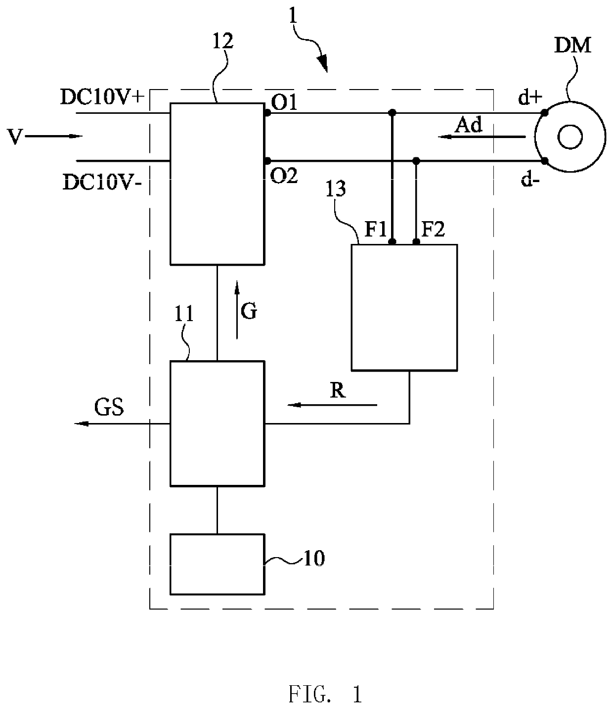
[0032]Please refer to FIG. 1, which illustrates a block diagram of a polarity correction circuit for dimmer according to the present invention. As shown, the polarity correction circuit for dimmer (short for polarity correction circuit 1) may be connected to a dimmer DM, and the polarity correction circuit 1 comprises a control circuit 11, an adjustment circuit 12, a detection circuit 13, and a power supply 10.
[0033]The power supply 10 is connected to the control circuit 11 to provide electricity for the control circuit 11 so as to drive the control circuit 11.
[0034]The adjustment circuit 12 is connected to the control circuit 11, a working voltage input end, and the dimmer DM, and the adjustment circuit 12 comprises a plurality of switches. The adjustment circuit 12 has a first dimming signal output end O1 and a second dimming signal output end O2 respectively connected to the positive electrode d+ and the negative electrode d− of the dimmer DM. The adjustment circuit 12 can receiv...
second embodiment
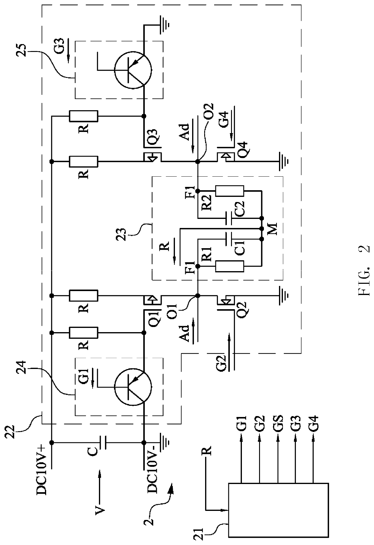
[0043]Please refer to FIG. 2, which illustrates a circuit diagram of a polarity correction circuit for dimmer according to the present invention. As shown, the polarity correction circuit for dimmer (short for polarity correction circuit 2) comprises a control circuit 21, an adjustment circuit 22, a detection circuit 23, a first auxiliary circuit 24, and a second auxiliary circuit 25.
[0044]The adjustment circuit 22 is connected to the control circuit 21 and the working voltage input end. The adjustment circuit 22 may be an H bridge circuit comprising a first transistor Q1, a second transistor Q2, a third transistor Q3, and a fourth transistor Q4. The adjustment circuit 12 has a first dimming signal output end O1 and a second dimming signal output end O2 respectively connected to the dimmer. The adjustment circuit 22 can receive the dimming signal Ad of the dimmer from the first dimming signal output end O1 and the second dimming signal output end O2. The working voltage input end in...
third embodiment
[0060]Please refer to FIG. 5, which illustrates a circuit diagram of a polarity correction circuit for dimmer according to the present invention. This embodiment provides an alternative available circuit configuration for achieving the invention concept of the present invention. As shown, the polarity correction circuit for dimmer (polarity correction circuit 3 for short) may be connected to a dimmer, and the polarity correction circuit 3 comprises a control circuit 31, an adjustment circuit 32, and a detection circuit 33.
[0061]In this embodiment, the adjustment circuit 32 may be an H-bridge circuit comprising a first transistor Q1, a second transistor Q2, a third transistor Q3, and a fourth transistor Q4. The detection circuit 33 comprises a first resistor R1, a first capacitor C1, a second resistor R2, and a second capacitor C2. The detection circuit 33 has a first detection end F1 and a second detection end F2. The detection circuit 33 detects the dimming signal Ad to generate a ...
PUM
 Abstract
Description
Claims
Application Information