Method for measuring a displacement

a technology of displacement and measurement method, applied in the field of displacement measurement method, to achieve the effect of increasing the reliability of the system and reducing the weight of the system

Active Publication Date: 2021-03-30
SAFRAN ELECTRONICS & DEFENSE
View PDF10 Cites 0 Cited by
  • Summary
  • Abstract
  • Description
  • Claims
  • Application Information

AI Technical Summary

Benefits of technology

[0010]An object of the invention is to reduce the weight and to increase the reliability of a system that comprises an inductive movement sensor and an electrical processor circuit.SUMMARY OF THE INVENTION
[0017]It is thus possible to omit the cable that is conventionally used for transmitting the excitation voltage, thereby reducing the weight of the system that comprises the inductive movement sensor and of the electrical processor circuit, while also increasing the reliability of said system.

Problems solved by technology

However, it frequently happens that the excitation voltage is not generated by the electrical processor circuit, but by an electrical generator circuit that is distinct from the electrical processor circuit and that is potentially situated at a certain distance away from the electrical processor circuit.

Method used


Image

  • Method for measuring a displacement
  • Method for measuring a displacement
  • Method for measuring a displacement

Examples


Embodiment Construction

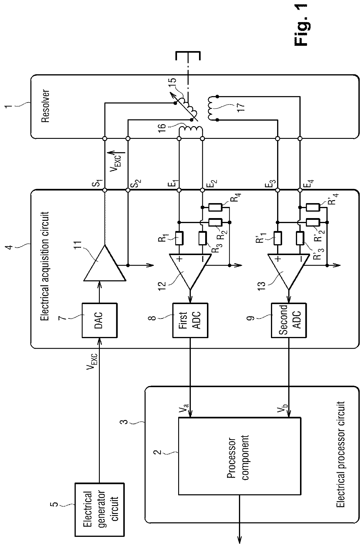
[0029]The measurement method in a first implementation of the invention is for measuring the angular position of a rotor of an electric motor of an electromechanical actuator.

[0030]With reference to FIG. 1, a resolver 1 is integrated in the electric motor. The resolver 1 comprises a stator and a rotor that is constrained to rotate with the rotor of the electric motor.

[0031]An angular movement of the rotor of the resolver 1 is measured in order to obtain an estimate of the angular position of the rotor of the electric motor.

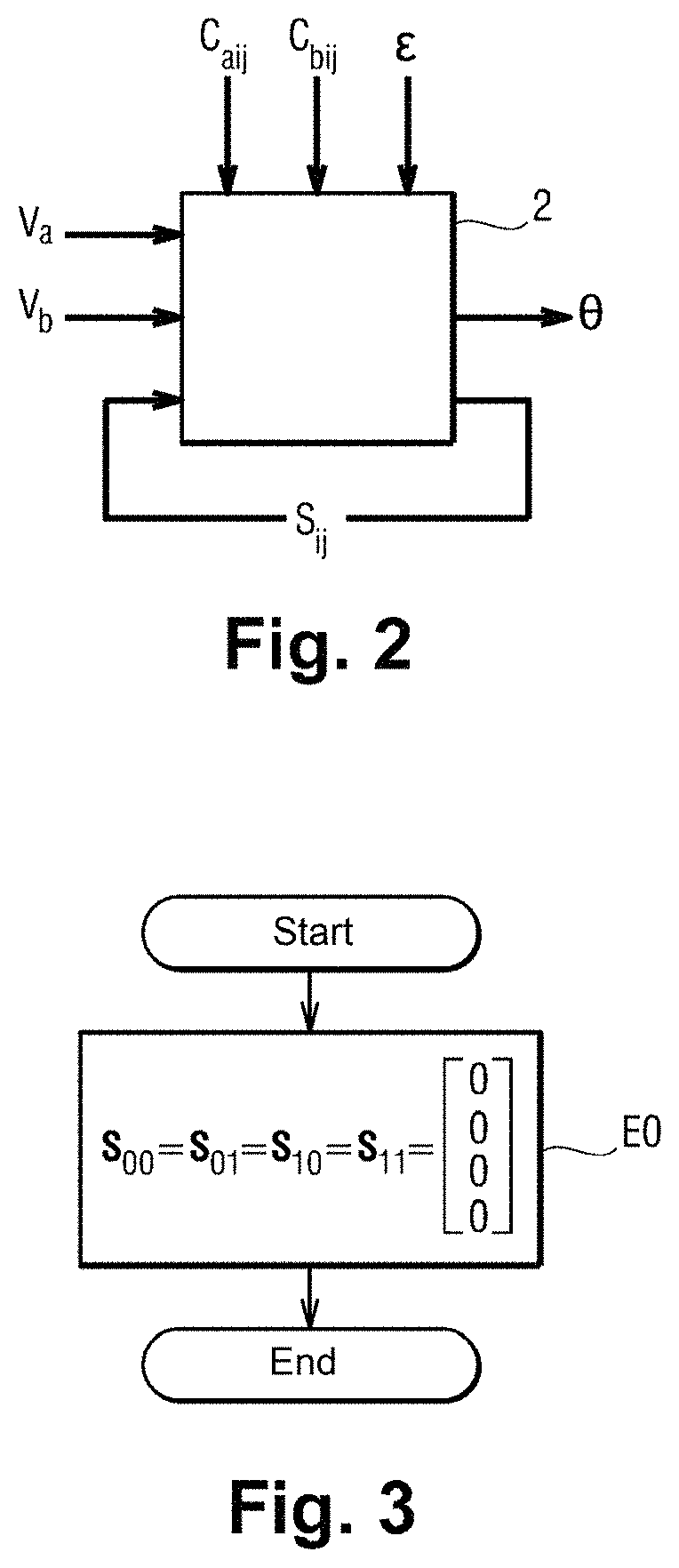
[0032]The measurement method is performed in a processor component 2 of an electrical processor circuit 3. The electrical processor circuit 3 is mounted on an electric circuit card integrated in a first piece of electrical equipment. By way of example, the first piece of electrical equipment is a computer, a data concentrator, a control unit, etc.

[0033]In this example, the processor component 2 is a field programmable gate array (FPGA), however it could be some ot...


PUM


Abstract

A method of measuring a movement, the method comprising the steps of: acquiring and digitizing both a first measurement voltage across the terminals of a first secondary winding and also a second measurement voltage across the terminals of a second secondary winding of an inductive movement sensor; multiplying the first measurement voltage by itself in order to obtain a first component of a crossed vector, multiplying the second measurement voltage by itself in order to obtain a second component of the crossed vector, and multiplying together the first measurement voltage and the second measurement voltage in order to obtain a third component of the crossed vector; applying the crossed vector as input to a lowpass filter in order to obtain a filtered vector, and estimating the movement from the components of the filtered vector.

Description

[0001]The invention relates to the field of methods of measuring a movement and that make use of an inductive movement sensor.BACKGROUND OF THE INVENTION[0002]Inductive movement sensors, such as linear variable differential transformers (LVDTs), rotary variable differential transformers (RVDTs), or resolvers are used in multiple applications in various industrial fields.[0003]In particular, numerous inductive movement sensors are to be found in modern aircraft, where electromechanical actuators are progressively replacing both actuators that are purely mechanical and also actuators that are hydraulic.[0004]Conventionally, such an inductive movement sensor includes a primary coil, a first secondary coil, and a second secondary coil. An excitation voltage is applied to the terminals of the primary coil. A first measurement voltage is generated across the terminals of the first secondary coil, and a second measurement voltage is generated across the terminals of the second secondary co...

Claims


Application Information

Patent Timeline
Patent Type & Authority Patents(United States)
IPC IPC(8): G01D5/22G06F17/00G01R23/167G01D5/20G06F17/16
CPCG01D5/2291G01D5/2073G01R23/167G06F17/00G06F17/16G06F2101/02G06F2101/04G06F2101/08
Inventor DEVELLE, OLIVIERMANCA, JEAN-LUC
Owner SAFRAN ELECTRONICS & DEFENSE
Why Eureka
Try Eureka