Power supply system

a power supply system and power supply technology, applied in emergency power supply arrangements, safety/protection circuits, electrochemical generators, etc., can solve the problems of difficulty in appropriately determining the modules that need replacement or other processes among the modules, one or more modules might suffer from a problem, and the number of operators can be reduced in the process of replacing batteries

Active Publication Date: 2021-03-30
TOYOTA JIDOSHA KK
View PDF2 Cites 0 Cited by
  • Summary
  • Abstract
  • Description
  • Claims
  • Application Information

AI Technical Summary

Benefits of technology

[0007]The power supply system of the configuration described above performs sweep control of sequentially switching the sweep module connected to the main line. When a problem is detected in one or more of the plurality of sweep modules, the controller continuously disconnects a failure sweep module in which the problem is detected, and excludes the failure sweep module and continues the sweep control. In the sweep module disconnected from the main line, a component (e.g., a battery module) suffering from the problem is replaced or repaired with safety. That is, in the power supply system with the configuration described above, only the component of the sweep module suffering from the problem can be replaced, for example, while operation of the entire system is maintained. When a problem occurs in one or more batteries, the voltage of the batteries to be replaced can be easily reduced to a smaller value than that in the case of replacing all the batteries included in a plurality of sweep modules. Thus, safety can be easily obtained. Working efficiency is higher than that in the case of replacing all the batteries. In addition, the power supply system with the configuration described above causes the indicator to indicate the sweep module in which the problem is detected. Thus, an operator can appropriately know which one of the plurality of sweep modules needs replacement or repairing, for example, of a component. Thus, in the power supply system with the configuration described above, replacement or repairing, for example, of the component suffering from the problem is appropriately performed without stopping of the entire operation.
[0010]In a preferred aspect of the power supply system disclosed here, attachment to the electric power circuit module and detachment from the electric power circuit module are performed using the battery module including the plurality of batteries as one unit. Thus, as compared to a case where the batteries suffering from a problem are replaced one by one, the number of jobs in replacing the batteries by an operator can be reduced.
[0011]In a preferred aspect of the power supply system disclosed here, the power supply system further includes a replacement detector that detects replacement of the battery module in which the problem is detected by another battery module. the controller is configured to perform a fourth process of performing the sweep control, by adding the sweep module in which the battery module is replaced to a connection target to the main line, and finishing an instruction by the indicator, in a case where the replacement detector detects replacement of the battery module. Thus, the operator can easily know that replacement of the battery modules can be appropriately finished. In addition, input / output of electric power to / from the outside appropriately continues with addition of the replaced battery module.

Problems solved by technology

In a power supply device including modules each including a battery, one or more of the modules might suffer from a problem (e.g., a problem occurring in the battery in the module) in some cases.
In such cases, if a component suffering from the problem is replaced by another component or is repaired, for example, with an operation of the entire power supply device stopped, efficiency will decrease.
In addition, in replacing or repairing one or more of the modules, for example, it is difficult for an operator to appropriately determine modules that need replacement or other processes among the modules in the power supply device.

Method used


Image

  • Power supply system
  • Power supply system
  • Power supply system

Examples


Embodiment Construction

[0017]One exemplary embodiment of the present disclosure will be described hereinafter in detail with reference to the drawings. Matters not specifically mentioned in the description but required for carrying out the disclosure can be understood as matters of design variation of a person skilled in the art based on related art in the field. The present teaching can be carried out on the basis of the contents disclosed in the description and common general knowledge in the field. In the drawings, members and parts having the same functions are denoted by the same reference numerals. In addition, dimensional relationship in each drawing does not reflect an actual dimensional relationship.

Schematic Overall Configuration

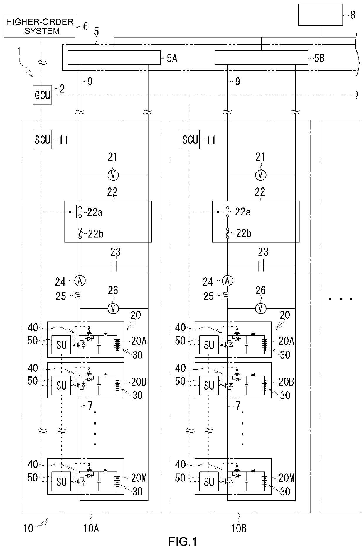
[0018]With reference to FIG. 1, an overall configuration of the power supply system 1 according to this exemplary embodiment will be schematically described. The power supply system 1 performs either output of electric power to a distribution device 5 connected to a high...


PUM


Abstract

The present teaching provides a power supply system capable of appropriately performing replacement or repairing of a component of a module where a problem occurs without stopping the entire operation, in a case where the problem occurs in of the module in a plurality of modules. The power supply system includes a plurality of sweep modules, a problem detector, an indicator, and a controller. Each sweep module includes a battery module and an electric power circuit module. The problem detector detects a problem for each sweep module. The indicator indicates a sweep module in which a problem is detected. In a case where a problem is detected in the sweep module (S4: YES), the controller causes the indicator to indicate a failure sweep module in which the problem is detected (S5). The controller disconnects the failure sweep module from a main line, and continues sweep control (S6 through S8).

Description

CROSS REFERENCE TO RELATED APPLICATIONS[0001]This application claims the benefit of priority to Japanese Patent No. 2018-222764 filed on Nov. 28, 2018. The entire contents of this application are hereby incorporated herein by reference.BACKGROUND1. Technical Field[0002]The present teaching relates to a power supply system including a plurality of modules each including a battery and a circuit.2. Description of the Related Art[0003]A power supply device known to date includes a plurality of modules each including a battery and a circuit, and each of the modules is controlled to perform at least one of outputting of electric power to the outside and storing of electric power input from the outside. For example, a power supply device described in Japanese Patent Application Publication No. 2018-74709 includes a plurality of battery circuit modules each including a battery, a first switching device, and a second switching device. The battery circuit modules are connected in series throu...

Claims


Application Information

Patent Timeline
Patent Type & Authority Patents(United States)
IPC IPC(8): H02J9/06H02J13/00H02J7/00
CPCH02J9/061H02J7/0068H02J13/0096H02J7/0063H01M10/482Y04S20/12Y02B90/20H02J1/08H02J1/001H02J7/0018H02J2207/20Y02E60/10Y02T10/70H02J7/0031H02J7/0047H02J3/02
Inventor YASOSHIMA, JUNIIZUMI, JUNTAKIMURA, KENJIKATSUDA, TOSHIHIROMATSUURA, KOHEIMATSUMOTO, JUNICHITOMURA, SHUJIGOTO, SHIGEAKIYANAGIZAWA, NAOKITANEMURA, KYOSUKEOOTSUKA, KAZUOBAN, TAKAYUKINISHI, HIRONOBU
Owner TOYOTA JIDOSHA KK
Why Eureka
Try Eureka