Supercharge Your Innovation With Domain-Expert AI Agents!

Pin fin heat sink with integrated phase change material and method

a heat sink and phase change technology, applied in the field of heat sinks, can solve the problems of periodic load transients, steep rise in the temperature of electronic devices, and the thermal capacity of cooling fluid may be exceeded

Active Publication Date: 2021-04-06
HAMILTON SUNDSTRAND CORP
View PDF14 Cites 0 Cited by
  • Summary
  • Abstract
  • Description
  • Claims
  • Application Information

AI Technical Summary

Problems solved by technology

Electronic devices such as those used for power electronics in aircraft applications or directed energy weapons often experience periodic load transients that produce peak thermal loads.
During times of peak thermal loads, the thermal capacity of the cooling fluid may be exceeded leading to a steep rise in the electronic device temperature.
Alternatively, a temporary reduction in the cooling capacity of the heat sink can also lead to a significant rise in the electronic device temperature.

Method used


Image

  • Pin fin heat sink with integrated phase change material and method
  • Pin fin heat sink with integrated phase change material and method

Examples


Embodiment Construction

[0013]A detailed description of one or more embodiments of the disclosed apparatus and method are presented herein by way of exemplification and not limitation with reference to the Figures.

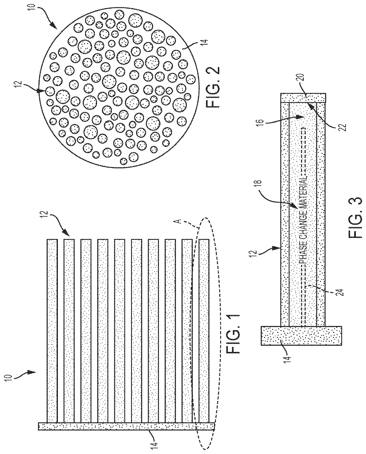
[0014]Referring to FIGS. 1 and 2, a portion of a pin fin heat sink is illustrated and generally referenced with numeral 10. In order to increase the surface area exposed to a cooling fluid in a cooling fluid passage, and thereby increase the heat transfer potential of the heat sink, a plurality of thermally conductive pins 12 are provided. The pins 12 conduct heat away from a zone to be cooled and into the cooling fluid passage, thereby exposing more surface area to the cooling fluid flowing through the cooling fluid passage. Since the amount of heat dissipated in the heat sink 10 is proportional to the surface area exposed to the cooling fluid, and the pins 12 generate more exposed surface area, the efficiency of the heat sink 10 is increased.

[0015]As shown, a plurality of pins 12 are operativel...


PUM


Abstract

A pin fin heat sink includes a plurality of pin fins extending from a base plate, at least one of the plurality of pin fins defining a hollow portion therein. The pin fin heat sink also includes an annular ring of metal foam material disposed within the hollow portion, the annular ring of metal foam material having a radially outer surface in direct contact with an inner diameter of the pin fin, the annular ring of metal foam material defining a central cavity. The pin fin heat sink further includes a phase change material disposed within the central cavity.

Description

CROSS-REFERENCE TO RELATED APPLICATION[0001]This application is a continuation-in-part of U.S. patent application Ser. No. 15 / 280,074, filed Sep. 29, 2016, the disclosure of which is incorporated herein in its entirety.BACKGROUND[0002]Exemplary embodiments pertain to the art of heat sink and, more particularly, to a pin fin heat sink, as well as a method of manufacturing a pin fin heat sink.[0003]Heat sinks capable of drawing heat from one place and dissipating it in another place are known and are used in numerous applications where efficiently removing heat is desirable. One type of heat sink used in fluid cooling systems dissipates heat from two parallel fluid passages into a cooling fluid passage between the passages. A cooling fluid (such as air) is then passed through the cooling fluid passage. Heat from the parallel fluid passages is drawn into the cooling fluid passage and is expelled at the opposite end of the heat sink with the cooling fluid.[0004]Electronic devices such a...

Claims


Application Information

Patent Timeline
Patent Type & Authority Patents(United States)
IPC IPC(8): F28D20/02F28F3/02H01L23/373H01L23/427
CPCF28D20/023F28F3/022H01L23/3733H01L23/3736H01L23/427F28F3/02F28F2215/04F28F2215/06Y02E60/14
Inventor BOURAS, SCOTT R.
Owner HAMILTON SUNDSTRAND CORP
Features
  • R&D
  • Intellectual Property
  • Life Sciences
  • Materials
  • Tech Scout
  • Unparalleled Data Quality
  • Higher Quality Content
  • 60% Fewer Hallucinations
Learn More