Charger

a charger and charging circuit technology, applied in the field of chargers, can solve the problems of difficulty in suppressing the heat generation of the electrical components of the charger with an increased charge current, and the charger may malfunction, and achieve the effects of efficient discharge, efficient cooling, and efficient suction of outside air

Active Publication Date: 2021-04-20
MAKITA CORP
View PDF17 Cites 0 Cited by
  • Summary
  • Abstract
  • Description
  • Claims
  • Application Information

AI Technical Summary

Benefits of technology

[0013]In a eighth aspect of the present disclosure, a drain hole is formed on the bottom part of the housing in a region surrounded by the first vertical wall or the second vertical wall that is configured to receive water that drops down the intake hole or the exhaust hole. Because of this configuration, water, which enters from the intake hole or the exhaust hole of the upper portion of the housing to the interior of the housing, drops and remains within the region surrounded by the first vertical wall or the second vertical wall, can be efficiently discharged by the drain hole.
[0014]In a ninth aspect of the present disclosure, the cooling fan is disposed in the vicinity of the first vertical wall or the second vertical wall such that an axis about which the cooling fan rotates is approximately horizontal in the left-to-right direction, and an intake side of the cooling fan is directed to the intake hole as seen in a plan view. Because of this configuration, the cooling fan can efficiently suck outside air from the intake hole. In addition, the cooling fan can flow the air along the electrical circuit board in the housing, and thus the electrical components on the electrical circuit board can be efficiently cooled.

Problems solved by technology

However, in the configuration present in the prior art, such as the prior art mentioned above, where the cooling fan is used for cooling the battery as well as for cooling the charger, it may be difficult to suppress heat generation of the electrical components of the charger with an increased charge current.
Because of this deficiency, it is necessary to provide a dedicated cooling fan in the housing of the charger for cooling the electrical components separately from a cooling fan for cooling the battery.
Additionally, in the case where both the intake hole and the exhaust hole are provided in the housing of the charger, if water that enters from the exhaust hole etc. and reaches the electrical components and the electrical circuit board, there is a risk that the charger may malfunction, which is to be countermeasured.

Method used


Image

  • Charger
  • Charger
  • Charger

Examples


embodiment 1

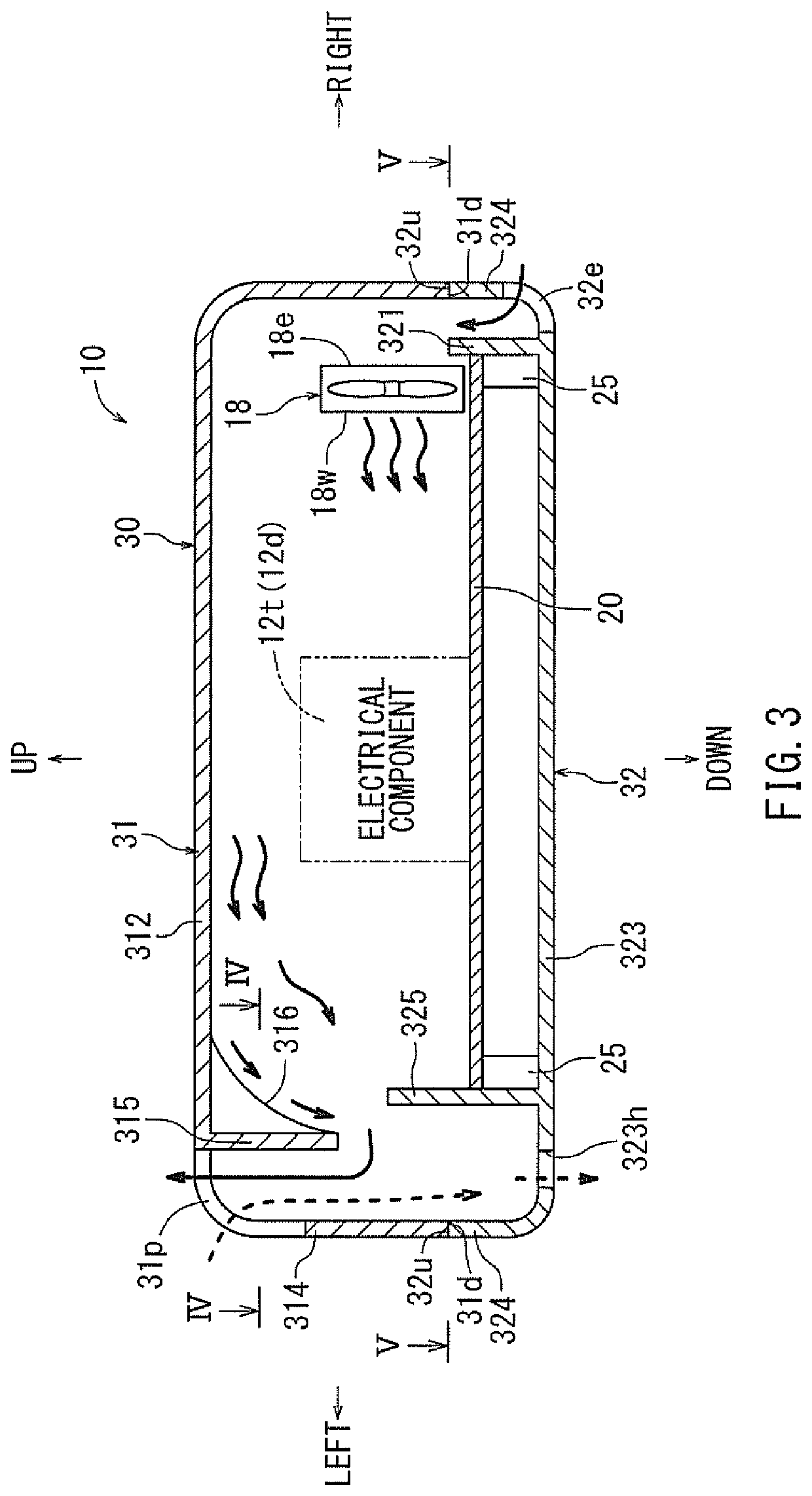
[0028]A charger according to an embodiment 1 of the present invention will be described below with reference to FIGS. 1 to 10. A charger 10 according to the present invention is a charger for charging a battery 50 used for an electric power tool. The front, rear, left, right, up and down directions shown in the figures correspond to the front, rear, left, right, up and down directions relative to the charger 10.

[0029]10>

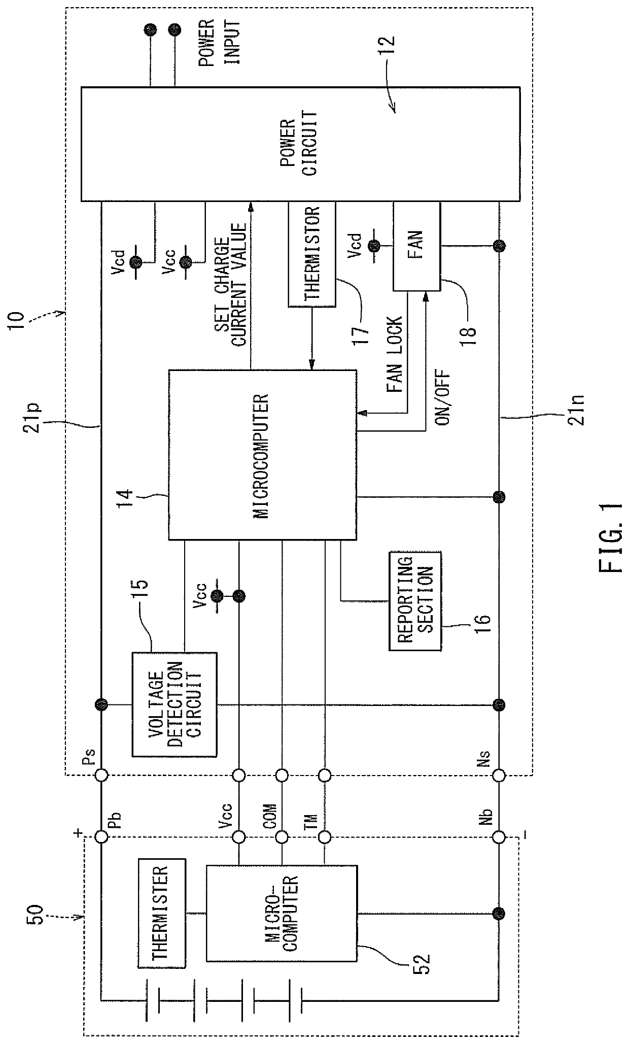
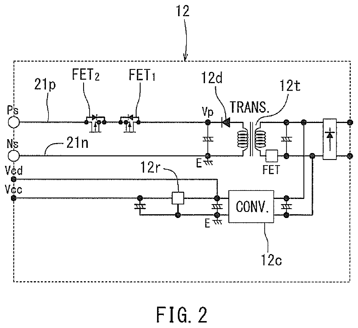
[0030]As shown in FIG. 1 depicting a wiring block diagram, the charger 10 comprises an electric power circuit 12, a microcomputer 14, a cooling fan 18 and a voltage detection circuit 15 etc. As shown in FIG. 2, the electric power circuit 12 is an electric circuit including a DC power source (Vp) for charge as well as a DC power source (Vcd, Vcc) for control by converting AC power from a domestic AC power source (power source input, e.g. mains) to DC power. The DC power source (Vp) for charge in the electric power circuit 12 is a power source used for charging the bat...


PUM


Abstract

A charger is provided with an intake hole through which outside air may flow into the interior of and through the body of the charger, and an exhaust hole from which the outside air is discharged through by the driving a cooling fan. A first vertical wall that surrounds the intake hole or a region exposed to water that drops down the intake hole in a fence-shaped manner, and a second vertical wall that surrounds the exhaust hole or a region exposed to water that drops down the exhaust hole in a fence-shaped manner are provided on a bottom plate of the housing. An electrical circuit board is disposed outward of an area where the first vertical wall surrounds the intake hole and also disposed outward of an area where the second vertical wall surrounds the region exposed to water that drops down the exhaust hole etc.

Description

TECHNICAL FIELD[0001]The present invention relates to a charger with a housing including an electrical circuit board and a cooling fan.BACKGROUND ART[0002]Generally, a battery generates heat when charged. When, due to the heat generation of the battery, the temperature of the battery exceeds a predetermined value, charging efficiency decreases. To mitigate the effects of the temperature increase, a cooling fan for cooling the battery being charged is provided within the charger. In a charger in the prior art disclosed in Japanese Laid-Open Patent Publication No. 2013-192282, a cooling fan, which is attached to a fan case, is housed in the charging housing. An air inlet of the fan case is in fluid communication with an intake hole provided on a side surface of the housing, and a blow-off outlet of the fan case is configured to be connectable to the battery on the upper surface of the housing. Furthermore, the fan case is provided with an opening for guiding a part of the airflow in t...

Claims


Application Information

Patent Timeline
Patent Type & Authority Patents(United States)
IPC IPC(8): H05K7/20H02J7/00
CPCH05K7/20909H02J7/00H02J7/0042H05K7/20H05K7/20145H05K7/20172H05K7/20181H02J2207/20Y02E60/10Y02E60/13H02J7/02
Inventor TAGA, HIDEYUKI
Owner MAKITA CORP
Why Eureka
Try Eureka