Battery pack
a battery module and battery technology, applied in the direction of battery/fuel cell control arrangement, vehicle sub-unit features, electric devices, etc., can solve the problems of voltage imbalance between the battery modules and the corresponding battery modules, and achieve the effect of minimizing the imbalance between the battery modules and minimizing the deviation of current consumption
- Summary
- Abstract
- Description
- Claims
- Application Information
AI Technical Summary
Benefits of technology
Problems solved by technology
Method used
Image

Examples
first embodiment
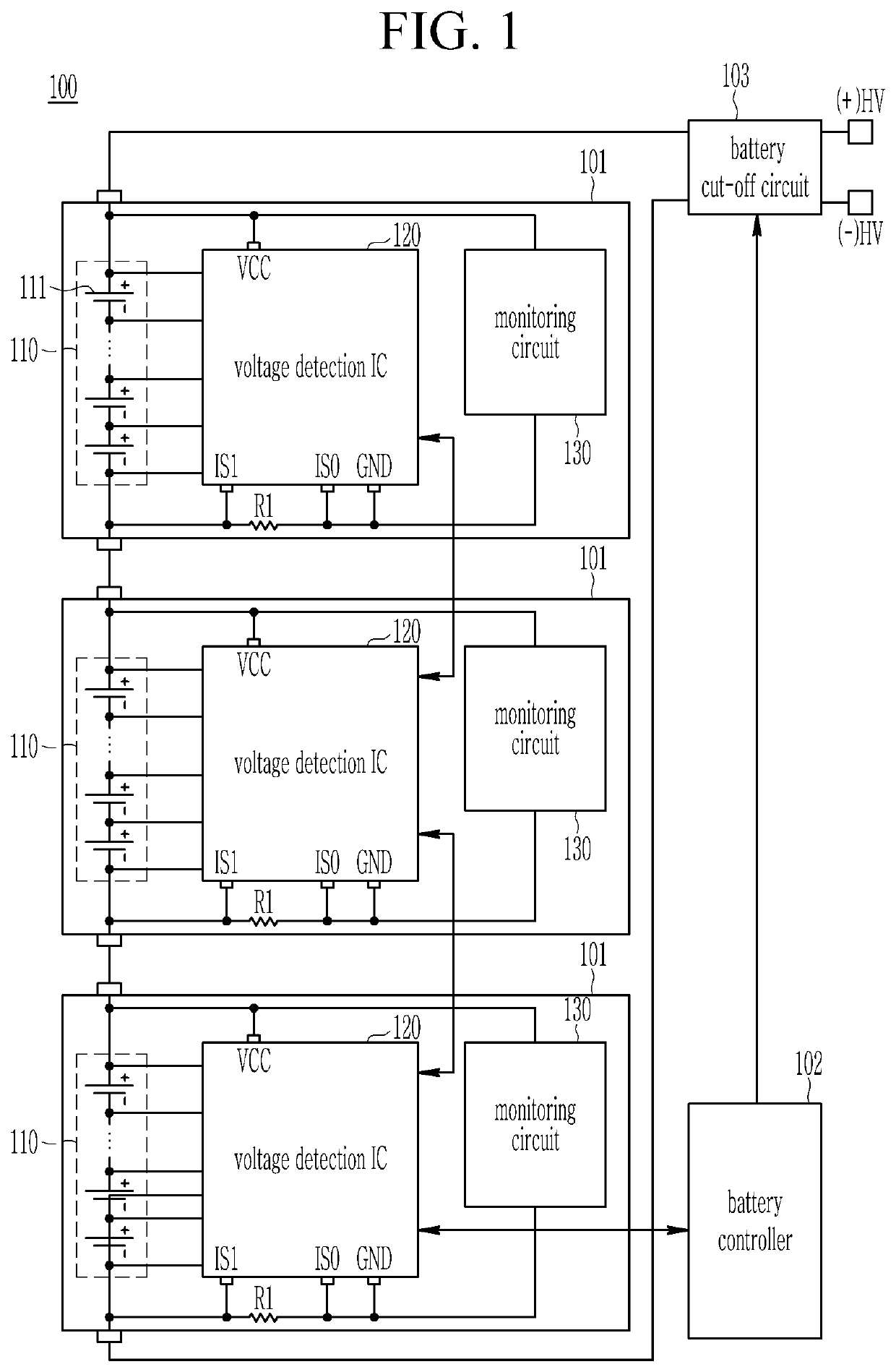
[0040]Referring to FIG. 1, a battery pack 100 may include a plurality of battery modules 101, a battery controller 102, and a battery cut-off circuit 103. Although a case where the battery pack 100 includes three battery modules 101 connected in series with each other is illustrated in FIG. 1 as an example, the present invention is not limited thereto, and a number of the battery modules 101 included in the battery pack 100 may be changed depending on an exemplary embodiment.
[0041]Each of the battery modules 101 includes a cell stack 110 and a voltage detection integrated circuit (IC) 120. Each of the battery modules 101 may further include a monitoring circuit 130 such as a temperature sensor in addition to the voltage detection IC 120.
[0042]Each cell stack 110 may include a plurality of cells 111 electrically connected to each other. Although a case where one cell stack includes a plurality of cells 111 connected in series with each other is illustrated in FIG. 1 as an example, t...
fifth embodiment
[0073]Referring to FIG. 6, a battery pack 200 may include a plurality of battery modules 201, a battery controller 202, and a battery cut-off circuit 203.
[0074]Each of the battery modules 201 includes a cell stack 210, a plurality of balancing resistors Rb, and a voltage detection IC 220. Each of the battery modules 201 may further include a monitoring circuit 230 such as a temperature sensor in addition to the voltage detection IC 220.
[0075]Each cell stack 210 may include a plurality of cells 211 electrically connected to each other.
[0076]The balancing resistors Rb may be connected between the corresponding cell and the voltage detection IC 220 to serve to discharge the corresponding cells.
[0077]The voltage detection IC 220 may serve to detect a cell voltage of each of the cells 211 included in the corresponding cell stack 210, and a total voltage of the corresponding cell stack 210 through a voltage detection circuit (not illustrated).
[0078]The voltage detection IC 220 may contro...
sixth embodiment
[0097]Referring to FIG. 8, the battery pack 300 may include a plurality of battery modules 301, a battery controller 302, and a battery cut-off circuit 303.
[0098]Each of the battery modules 301 includes a cell stack 310, a voltage detection IC 320, and a current adjustment circuit 340. Each of the battery modules 301 may further include a monitoring circuit 330 such as a temperature sensor in addition to the voltage detection IC 320.
[0099]Each cell stack 310 may include a plurality of cells 311 electrically connected to each other.
[0100]The voltage detection IC 320 may serve to detect a cell voltage of each of the cells 311 included in the corresponding cell stack 310 and a total voltage of the corresponding cell stack 310 through a voltage detection circuit (not illustrated).
[0101]The voltage detection IC 320 may control cell balancing between the cells 311 included in the corresponding cell stack 310. The voltage detection IC 320 may control cell balancing by conducting or blocki...
PUM
 Abstract
Description
Claims
Application Information
 - R&D
- Intellectual Property
- Life Sciences
- Materials
- Tech Scout
- Unparalleled Data Quality
- Higher Quality Content
- 60% Fewer Hallucinations
Browse by: Latest US Patents, China's latest patents, Technical Efficacy Thesaurus, Application Domain, Technology Topic, Popular Technical Reports.
© 2025 PatSnap. All rights reserved.Legal|Privacy policy|Modern Slavery Act Transparency Statement|Sitemap|About US| Contact US: help@patsnap.com